Replacing the Power Supply (P/N 330020-623) Before Turning Off Power
11
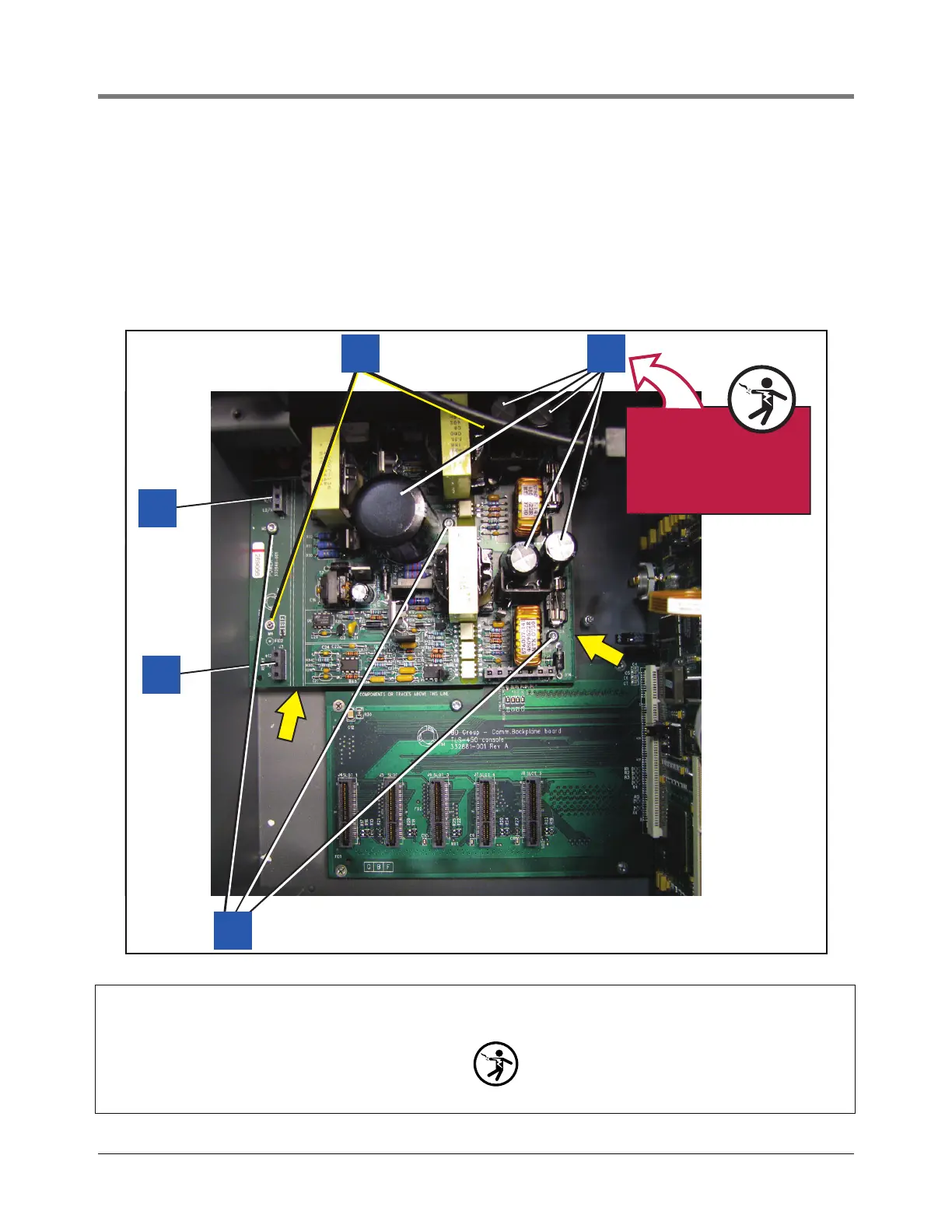
8. Remove the three #6 taptite screws (item 1 in Figure 8) that secure the Power Supply board to the console
housing.
9. Place fingers under the Power Supply board (at locations indicated by two arrows in Figure 8) and lift the
board up until it is free of the two retention pins (item 3 in Figure 8).
10. Disconnect the printer power cable from the Power Supply board.
11. Lift the board out of the console by its edges since there is still undischarged high voltage in the big
capacitors.
Figure 8. Removing Power Supply
Legend for numbered boxes in Figure 8
956-6.eps
1
5
WARNING!
Shock hazard. Do not
touch underside of
board beneath these
five capacitors.
4
3
2
1. #6 taptite screws
2. J3 - Low voltage relay control connector
3. J2 - AC Input module power connector
4. Two board retention pins.
5. Capacitors
WARNING! These caps can hold a high charge,
do not touch underside of board where these
caps are soldered to board.
 Loading...


