Replacing the Display Door Assembly (P/N 330020-625) Before Turning Off Power
5
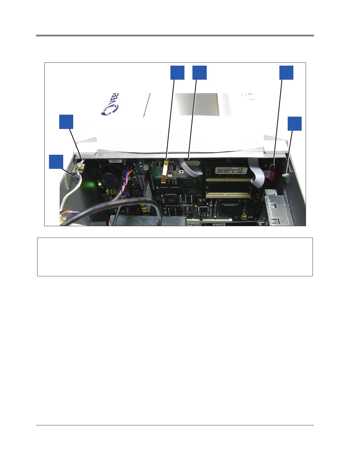
Figure 3. Display door cables
Legend for numbered boxes in Figure 3
8. Reconnect the three cables from the Display door to their connectors on the CPU board (see Figure 3).
9. Close the Display door and insert the right-side top and bottom #8 taptite screws. Tighten the two screws.
10. Close the Printer door and insert the right-side top and bottom #8 taptite screws. Tighten the two screws.
1. Top Display door hinge shoulder screw
2. Grounding braid
3. Touchscreen control cable
4. Display data cable
5. LED/Display cable
6. Bottom Display door hinge shoulder screw
 Loading...


