1
Introduction
This manual contains procedures for installation or replacement of the following TLS-450PLUS console modules:
The above parts are for the TLS system designed and manufactured by Veeder-Root. This manual assumes all
preliminary site preparation is completed, and that field wiring from the console to the sensor junction box is in
place. If site preparation is necessary, refer to the TLS-450PLUS Site Prep and Installation manual, or contact your
Veeder-Root representative for assistance. Also included in this manual is the procedure for upgrading software
features.
Related Manuals
577014-073 TLS-450PLUS Site Prep And Installation Manual
577013-401 POS Application Guide
577014-110 TLS-450PLUS/TLS4 Operator's Manual
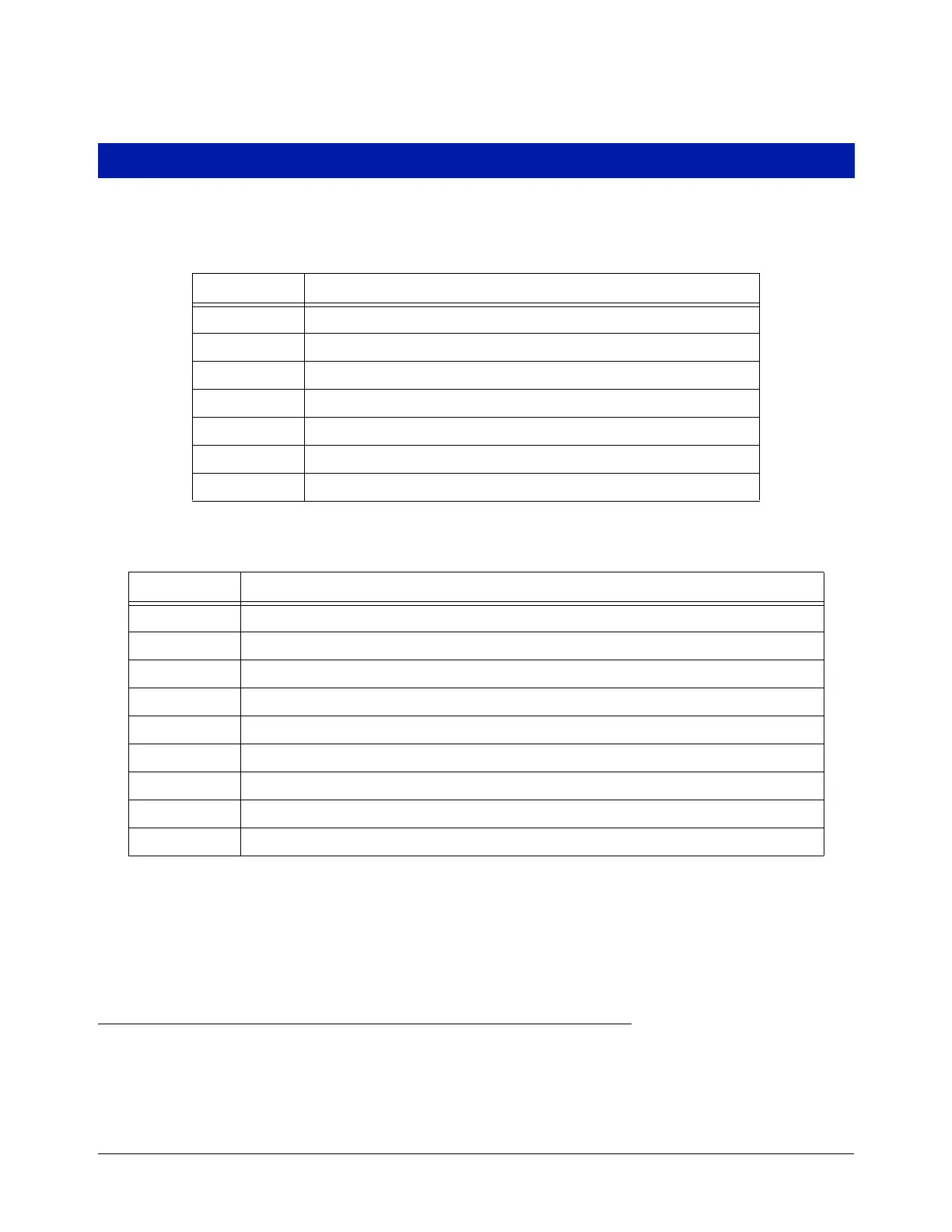
Table 1. Module Bay Modules
Part No. Item
332812-001 Universal 16 Sensor/Probe Interface Module
332813-001 Universal Input/Output Interface Module
332812-005 MDIM Module
332812-004 LVDIM Module
333564-001 10 Amp Controller Interface Module
332812-006 Universal 16 Sensor/Probe Interface Module w/ATM Pressure Board
332665-001 ATM Board
Table 2. Communication Bay Modules
Part No. Item
332818-001 SiteFax/Modem Single Port Module
333460-001 Ethernet Module
333477-001 USB module
332866-001 RS-232 Single Port Module (also used for EDIM or Satellite S-SAT or Satellite H-JBox Modules apps.)
332868-001 RS-232 Dual Port Module (also used for EDIM or Satellite S-SAT or Satellite H-JBox Modules apps.)
332867-001 RS-485 Single Port Module
332869-001 RS-485 Dual Port Module
333140-001 CDIM Module
333651-001 IFSF LON Module