Do you have a question about the Vega EL 31 and is the answer not in the manual?
The described module must only be installed and operated as described in this operating instruction. Please note that other action can cause damage for which VEGA does not take responsibility.
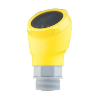
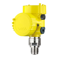
Capacitive electrodes EL detect levels of virtually any medium unaffected whether liquids, powders or pastes. This is also valid for adhesive products.
Overview of available electrode types and their versions, including oscillators, approvals, mechanical connections, and materials.
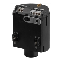
Detailed specifications for housing, mechanical connection, electrode materials, length, isolation, ambient conditions, and oscillator CAP E32 Ex/H Ex.
Information on explosion protection, overfill protection, ship approvals, CE compliance, and Zone 2 usage.
Diagrams showing the physical dimensions for various EL electrode types, including overall length and isolation details.
Explanation of the configuration and data presented on the instrument's type plate for proper identification and setup.
Guidelines for installing the electrode, considering lateral load, extraction forces, pressure, and ensuring correct vessel connection.
Instructions for safely connecting the sensor, including switching off power and connecting supply voltage according to diagrams.
Diagrams illustrating the electrical wiring for connecting the sensor to terminals, indicating supply voltage and current output.
Procedure for adjusting the electrode using the original medium or dry adjustment methods, with reference to connection diagrams.
Detailed steps for adjusting min/max levels, integration time, reverse characteristics, and sensor optimization using keys and switches.
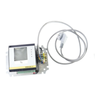
Guide for adjusting the electrode via PC using VEGA Visual Operating (VVO) software, including system requirements and configuration.
Instructions for adjusting the sensor using a HART®-handheld device, covering multidrop and burst operation modes.
Enabling simulation of filling levels via VVO or HART®-handheld to test connected instruments and alarm functions.
Information stating that the instrument is maintenance free.
Procedure for returning defective instruments to VEGA-staff for repair, including a description of the error.
Troubleshooting guide for common failures like current values out of range, checking connections, and diagnosing oscillator or electrode defects.
| Brand | Vega |
|---|---|
| Model | EL 31 |
| Category | Measuring Instruments |
| Language | English |