Do you have a question about the Vega VEGAPULS 64 and is the answer not in the manual?
Provides information for mounting, connection, setup, maintenance, and safety of the instrument.
Explains symbols for document ID, tips, notes, cautions, warnings, danger, Ex applications, lists, and actions.
Operations must be carried out by trained, qualified personnel wearing protective equipment.
Instrument must be operated in flawless condition; operator is responsible. Observe regulations and safety rules.
Instrument tested per harmonized standards; approved for use in EU countries.
Approval valid for USA; complies with FCC rules. Conditions for use inside/outside closed vessels.
Installations in US/Canada must comply with relevant electrical codes; Class 2 power supply required.
Details scope of delivery for VEGAPULS 64 sensor, accessories, and documentation.
Explains the layout and content of the instrument's type label for identification.
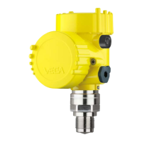
VEGAPULS 64 is a radar sensor for continuous level measurement of liquids using radar signals.
Details packaging materials, transport considerations, and storage conditions for the instrument.
Provides general instructions for mounting, including protection against moisture and process conditions.
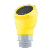
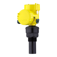
Details mounting options for plastic horn antenna, including mounting strap.
Details two versions for flange mounting: Combi compression flange and Adapter flange.
Instructions for assembling the mounting strap to the sensor, including angle of inclination options.
Provides instructions on polarization, installation position, and avoiding false echoes.
Nozzle should be short and rounded; antenna end should protrude from nozzle.
Avoid obstructions; ensure clear view to product. Use false signal suppression if needed for vessel installations.
General observations for flow measurement setup: upstream mounting, center installation, distance to orifice.
Safety instructions, voltage supply, connection cable, and cable glands preparation for power connection.
Power supply and signal on two-wire cable; use energy-limited circuit (Class 2).
Connect cable screening to ground potential for shielded cables; consider potential differences.
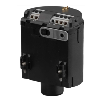
Details connection technology via spring-loaded terminals and connection procedure for modules/adapters.
Illustrates wiring for single chamber housing, applicable to non-Ex and Ex-ia versions.
Illustrates wiring for double chamber housing, applicable to non-Ex and Ex-ia versions.
Shows wire assignment for permanently connected cables for IP66/IP68, 1 bar version.
Describes the self-test sequence after connecting power, including status messages and output signal behavior.
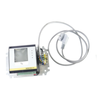
Instructions for inserting and removing the display/adjustment module in various positions without interrupting power.
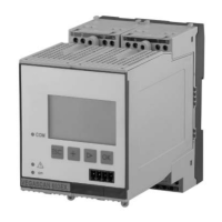
Introduces the adjustment system, LC display, and adjustment keys for instrument configuration.
Describes different measured value indication modes and how to select the national language.
Guides users through quick setup to adapt the sensor to the application using the display module.
Introduces extended adjustment via main menu sections: Setup, Display, Diagnostics, Additional adjustments, Info.
Procedure for setting the maximum level (minimum measuring distance) and corresponding percentage.
Safeguarding sensor parameters against unauthorized modifications using a PIN.
Simulating measured values via current output for testing signal paths and downstream instruments.
Recommendations for documenting or saving parameter adjustment data for reuse or service.
Connecting the PC directly to the sensor or via HART to the signal cable using interface adapters.
Using PACTware and DTMs for parameter adjustment. Details on standard/full versions and downloads.
Recommends documenting or saving parameterisation data via PACTware for multiple use or service.
Using DD adjustment programs like AMS™ and PDM with EDD files downloadable from www.vega.com.
Parameterization with Field Communicator 375/475 using EDDs and Easy Upgrade Utility software.
No special maintenance required for proper use. Measures against buildup and cleaning instructions.
Instrument memory for diagnostic purposes: measured values, event types, and status messages.
Instrument self-monitoring and diagnostics according to NE 107, status messages, and pictographs.
Table of failure codes (F013-F260), causes, rectification steps, and DevSpec states.
Lists error codes for setup, function check, out of specification, and maintenance, with rectification.
Operator responsibility for fault rectification; measures include evaluating messages and checking output.
Troubleshooting common errors in the 4-20 mA signal, such as instability, missing signal, or incorrect levels.
Examples of measurement errors with constant level, including low/high values and jumps towards 0%.
Examples of measurement errors during filling, such as unchanged values, jumps, or incorrect levels.
Examples of measurement errors during emptying, including unchanged values or jumps towards 0%.
Procedure for replacing a defective electronics module, including ordering and loading settings.
Required components and procedure for updating instrument software via PC and PACTware.
Warning about process conditions before dismounting; reverse mounting steps.
Instrument materials are recyclable. Follow WEEE directive and contact for disposal if needed.
Lists materials for wetted and non-wetted parts, including antenna, seals, and housing components.
Details housing materials, weights, and maximum torques for threads, flanges, and glands.
Specifies measured variable (distance), max measuring range, and output signal details (4-20mA/HART).
Details temperature drift, deviation due to conversion, and EMI effects on accuracy.
Lists measuring frequency, cycle time, step response time, and beam angles for different versions.
Details process temperature ranges for various antenna systems and materials.
Shows derating curves for ambient/process temperature with integrated horn antenna for different housings.
Shows derating curves for ambient/process temperature with plastic horn antenna.
Shows derating curves for ambient/process temperature with encapsulated antenna systems.
Shows derating curves for ambient/process temperature with encapsulated antenna systems up to +200°C and -196°C.
Lists process fittings, available versions, and corresponding process pressure ratings.
Specifies protection ratings (IEC 60529, NEMA) for different housing materials and versions.
Lists geographic positions of radio astronomy stations in Europe for radio license restrictions.
References where to download detailed dimensional drawings for various instrument versions.
| Frequency | 80 GHz |
|---|---|
| Process Temperature | -40 to 200 °C (-40 to 392 °F) |
| Accuracy | ±2 mm |
| Output Signal | 4 to 20 mA, HART, Modbus |
| Protection Class | IP66/IP67/IP68 |
| Process Fitting | Flange |
| Materials, Wetted Parts | PTFE, PEEK, 316L stainless steel |
| Housing Material | Aluminum, stainless steel |
| Material | Stainless steel (1.4404 / 316L), PTFE, PEEK |