45
6 Set up with the display and adjustment module
VEGAPULS 64 • Two-wire 4 … 20 mA/HART
51141-EN-210219
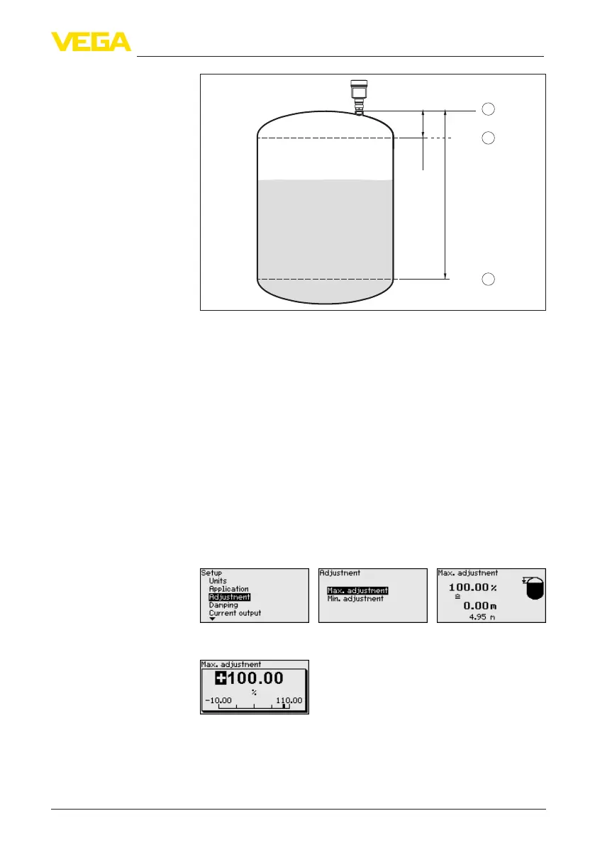
100%
0%
0,5 m
(19.68
")
5 m
(196.9
")
2
1
3
Fig. 41: Parameterisation example, Min./max. adjustment
1 Min. level = max. measuring distance
2 Max. level = min. measuring distance
3 Reference plane
If these values are not known, an adjustment with the distances of e.g.
10%and90%ispossible.Startingpointforthesedistancespecica-
tionsisalwaysthesealingsurfaceofthethreadorange.Youcannd
specicationsonthereferenceplaneinchapter"Technical data". The
actual level is calculated on the basis of these settings.
The actual product level during this adjustment is not important,
because the min./max. adjustment is always carried out without
changing the product level. These settings can be made ahead of
time without the instrument having to be installed.
Proceed as follows:
1. Select with [->]themenuitemMax.adjustmentandconrmwith
[OK].
2. Prepare the percentage value for editing with [OK] and set the
cursor to the requested position with [->].
3. Set the requested percentage value with [+] and save with [OK].
The cursor jumps now to the distance value.
Setup - Max. adjustment