56
7 Setup with PACTware
VEGAPULS 64 • Two-wire 4 … 20 mA/HART
51141-EN-210219
7 Setup with PACTware
7.1 Connect the PC
3
1
2
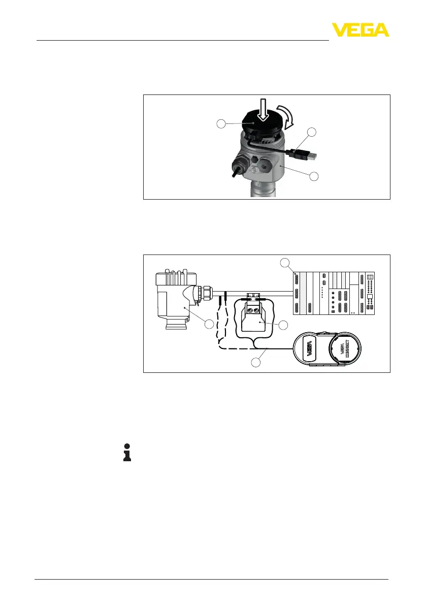
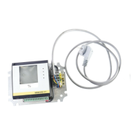
Fig. 42: Connection of the PC directly to the sensor via the interface adapter
1 USB cable to the PC
2 Interface adapter VEGACONNECT
3 Sensor
4
1
2
3
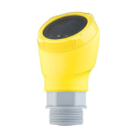
Fig. 43: Connecting the PC via HART to the signal cable
1 Sensor
2 HART resistance 250 Ω (optional depending on evaluation)
3 Connection cable with 2 mm pins and terminals
4 Processing system/PLC/Voltage supply
5 Interface adapter, for example VEGACONNECT 4
Note:
With power supply units with integrated HART resistance (internal
resistanceapprox.250Ω),anadditionalexternalresistanceisnot
necessary. This applies, e.g. to the VEGA instruments VEGATRENN
149A, VEGAMET 381, VEGAMET 391. Common Ex separators are
alsousuallyequippedwithasucientcurrentlimitingresistance.In
such cases, the interface adapter can be connected parallel to the
4 … 20 mA cable (dashed line in the previous illustration).
7.2 Parameter adjustment with PACTware
For parameter adjustment of the instrument via a Windows PC, the
congurationsoftwarePACTwareandasuitableinstrumentdriver
Via the interface adapter
directly on the sensor
Via the interface adapter
and HART
Prerequisites