30
5 Connecting to power supply
VEGAPULS 64 • Two-wire 4 … 20 mA/HART
51141-EN-210219
Note:
Prior to setup you have to replace these protective caps with ap-
proved cable glands or close the openings with suitable blind plugs.
On plastic housings, the NPT cable gland or the Conduit steel tube
must be screwed into the threaded insert without grease.
Max. torque for all housings, see chapter " Technical data".
If shielded cable is required, the cable screening must be connected
on both ends to ground potential. In the sensor, the cable screening
is connected directly to the internal ground terminal. The ground ter-
minal on the outside of the housing must be connected to the ground
potential (low impedance).
In Ex systems, the grounding is carried out according to the installa-
tion regulations.
In electroplating plants as well as plants for cathodic corrosion protec-
tionitmustbetakenintoaccountthatsignicantpotentialdierences
exist. This can lead to unacceptably high currents in the cable screen
if it is grounded at both ends.
Information:
Themetallicpartsoftheinstrument(processtting,sensor,concen-
tric tube, etc.) are connected with the internal and external ground
terminal on the housing. This connection exists either directly via
the conductive metallic parts or, in case of instruments with external
electronics, via the screen of the special connection cable.
Youcanndspecicationsonthepotentialconnectionsinsidethe
instrument in chapter " Technical data".
5.2 Connecting
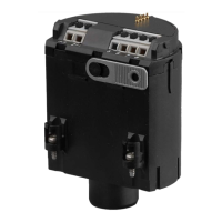
The voltage supply and signal output are connected via the spring-
loaded terminals in the housing.
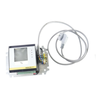
Connection to the display and adjustment module or to the interface
adapter is carried out via contact pins in the housing.
Information:
The terminal block is pluggable and can be removed from the
electronics. To do this, lift the terminal block with a small screwdriver
and pull it out. When reinserting the terminal block, you should hear it
snap in.
Proceed as follows:
1. Unscrew the housing lid
2. If a display and adjustment module is installed, remove it by turn-
ing it slightly to the left
3. Loosen compression nut of the cable gland and remove blind
plug
4. Remove approx. 10 cm (4 in) of the cable mantle, strip approx.
1 cm (0.4 in) of insulation from the ends of the individual wires
5. Insert the cable into the sensor through the cable entry
Cable screening and
grounding
Connection technology
Connection procedure
 Loading...