37
6 Set up with the display and adjustment module
VEGAPULS 64 • Two-wire 4 … 20 mA/HART
51141-EN-210219
1 2
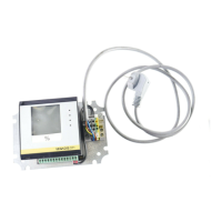
Fig. 38: Installing the display and adjustment module in the double chamber
housing
1 In the electronics compartment
2 In the connection compartment
Note:
Ifyouintendtoretrottheinstrumentwithadisplayandadjustment
module for continuous measured value indication, a higher lid with an
inspection glass is required.
6.2 Adjustment system
1
2
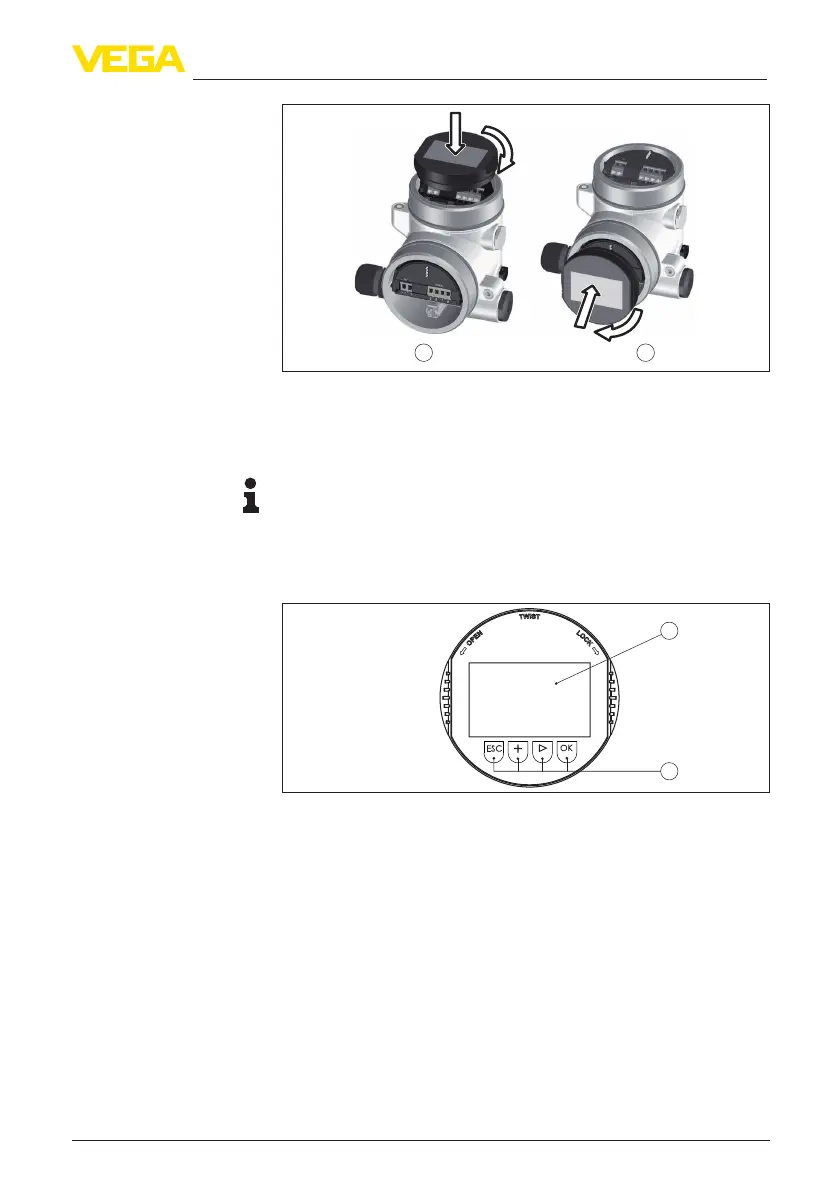
Fig. 39: Display and adjustment elements
1 LC display
2 Adjustment keys
•
[OK] key:
– Move to the menu overview
– Conrmselectedmenu
– Edit parameter
– Save value
•
[->] key:
– Change measured value presentation
– Select list entry
– Select menu items
– Select editing position
•
[+] key:
Key functions
 Loading...