Do you have a question about the Vega VEGABAR 52 and is the answer not in the manual?
Provides information for mounting, connection, setup, maintenance, and fault rectification.
Directs the manual to trained qualified personnel for proper use and practice.
Explains symbols for information, caution, warning, danger, Ex applications, lists, and actions.
Operations must be performed by trained specialist personnel authorized by the plant operator.
VEGABAR 52 is for gauge, absolute pressure, and vacuum measurement.
Incorrect use can lead to application-specific hazards like vessel overfill or damage.
Requires observance of regulations, safety instructions, and accident prevention rules.
Safety approval markings and safety tips on the device must be observed.
Device fulfills legal EC guidelines; CE mark confirms successful testing.
Measuring cell range vs. permissible process pressure must not be exceeded for safety.
Ex-specific safety information for installation and operation in Ex areas is provided.
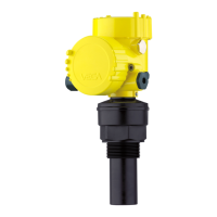
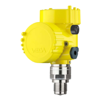
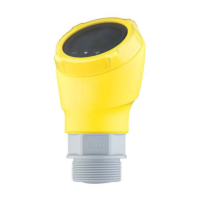
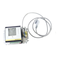
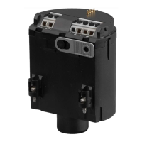
Details the scope of delivery and the main constituent parts of the VEGABAR 52.
The type label contains crucial data for instrument identification and use.
Explains the working principle of VEGABAR 52 in various industries and applications.
Describes the CERTEC® measuring cell, capacitance change, and signal output.
Lists adjustment media: indicating module, DTMs, AMS/PDM, and HART handheld.
Covers packaging, transport procedures, and storage conditions for the instrument.
Transport must consider notes on packaging; non-observance can cause damage.
Packages must be left closed and stored according to markings until installation.
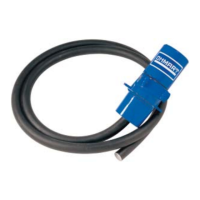
Details accessories like PLICSCOM, VEGACONNECT, and VEGADIS 61.
VEGADIS 62 for HART protocol indication/adjustment; also for sensors without HART.
Lists flange standards (DIN, EN, ANSI, JIS, GOST) and provides manual reference.
Replacement part for VEGABAR transmitters; one version per signal output.
Ensure process-exposed parts match process conditions (pressure, temp., chemistry).
Select accessible position; housing rotates 330°, module positions are 90° apart.
Lead connection cable downward to drain off rain/condensation water.
Ensure ambient temperatures do not exceed limits stated in 'Technical data'.
Details steps for welding sockets, sealing threads, and flange/hygienic fittings.
Steps for mounting external housing: marking holes and fastening wall mounting plate.
Follow safety instructions: connect only without line voltage, consider overvoltage arresters.
Power and signal on two-wire cable; voltage range depends on version. See 'Technical data'.
Use standard two-wire cable; screened if interference expected. Check diameter for gland seal.
Connect screen on both ends to ground potential; sensor to internal ground, housing to potential equalization.
Steps for connecting the sensor to external housing, including wiring and grounding.
Procedure for IP 68 external housing: loosen screws, remove housing socket, loop cable.
Diagram of electronics and connection compartment for single chamber housing.
Schematic of wiring for single chamber housing, showing voltage supply and signal output.
Diagram of electronics compartment for double chamber housing (non-Ex, Ex ia).
Diagram of connection compartment for double chamber housing.
Schematic of wiring for double chamber housing, showing voltage supply and signal output.
Diagram of electronics compartment for Ex d double chamber housing.
Diagram of connection compartment for Ex d double chamber housing.
Wiring plan for Ex d double chamber housing.
Illustrates wiring for IP 66/IP 68 (1 bar) version.
Overview of wiring for external housing with IP 68 (25 bar) version.
Diagram of electronics and connection compartment for power supply.
Shows connection of sensor in housing socket.
Wiring plan for external electronics, showing voltage supply.
Describes the self-check process upon connecting power supply or voltage recurrence.
PLICSCOM module for measured value display, adjustment, and diagnosis in various housings.
Procedure for inserting and removing the indicating and adjustment module.
Steps for mounting/dismounting the module: unscrew cover, place, press, screw back.
Details the indicating and adjustment elements and key functions.
Explains functions of [OK], [->], [+] and [ESC] keys for adjustment.
Guides through HART-Multidrop address setting and application modes.
Setting the address is required before parameter adjustment in HART-Multidrop mode.
Sequence for level measurement: select unit, position correction, min/max adjustment.
Switching measurement units (e.g., bar to mbar); density must also be entered.
Procedure to activate position correction and accept/edit measured value.
Procedure for minimum adjustment: edit % value, then mbar value.
Procedure for maximum adjustment: edit % value, then mbar value.
Sequence for process pressure: select application, unit, position correction, zero/span.
Switching application from Level to Process Pressure via Service menu.
Selects adjustment unit, e.g., bar to mbar, and temperature unit.
Procedure to activate position correction and accept/edit measured value.
Procedure for zero adjustment: edit mbar value, confirm, move to span.
Procedure for span adjustment: edit mbar value, confirm, move to menu overview.
Linearisation for non-linear vessel volumes; preprogrammed curves available.
Read or write parameter adjustment data to/from the sensor via the module.
Resets sensor-specific values to default settings.
Resets menu items like Zero/Min, Span/Max, Density, Damping to reset values.
Resets special parameters to default values; peak values reset to actual value.
Covers scaling, simulation, trend curve presentation.
Diagram showing the menu structure for Basic adjustment and Display sections.
Menu structure for unit, damping, position correction, min/max adjustment, linearization, sensor-TAG.
Menu structure for displayed value, lighting, display unit, and scaling.
Menu for peak value, sensor status, and trend curve.
Menu for output, simulation, reset, language, HART mode, copy data, PIN, application.
Menu for instrument type, serial number, calibration date, software version.
Instructions for connecting PC to sensor directly or externally via VEGACONNECT.
Diagram showing direct connection using USB cable and VEGACONNECT.
Diagram showing external connection via I²C bus and VEGACONNECT.
Connecting PC via HART to signal cable; necessary components listed.
Guides to setup with PACTware; requires DTM-Collection.
Instrument descriptions for AMS™/PDM are available as DD/EDD.
No special maintenance required in normal operation; clean diaphragm if buildup occurs.
Clean diaphragm if necessary; check material resistance and consult agency for special instructions.
Operator is responsible for fault rectification; check signals and error messages.
Check output signals, evaluate error messages, use PACTware for diagnostics.
Contact VEGA service hotline for urgent cases; available 7 days a week.
Check signal stability, level fluctuations, pressure compensation.
Lists error codes (E013, E017, E036, E041) and their meanings.
Explains total deviation calculation (Ftotal = Fperf + Fstab) with examples.
Defines total deviation as sum of basic accuracy and long-term stability.
Procedure for exchanging a defective electronics module with an identical type.
Details how to determine software version and required components for update.
Steps to download and extract sensor software files from www.vega.com.
Connect PC to instrument, start PACTware, and use project assistant for connection.
Steps to update sensor software using PACTware and extracted hex file.
Procedure for instrument repair: download return form, clean, pack, and ship.
Warning about dangerous conditions; reverse mounting and connection steps.
Instrument is recyclable; pass to specialized company, not municipal points.
Provides technical specifications including general data, materials, and weights.
Covers parameter, pressure, measuring principle, and communication interface.
Details materials for wetted and non-wetted parts, seals, and housing components.
Defines output signal (4-20 mA/HART), resolution, failure signal, and NAMUR recommendations.
Details run-up time, dead time, rise time, step response time, and damping.
Specifies processing via HART, Profibus PA, FF; range and resolution for temperature.
Specifies accuracy ranges in Celsius and Fahrenheit for different temperature ranges.
Details adjustment ranges for min/max, zero/span, and recommended turn down.
Table of nominal ranges and overload capacities in bar and kPa.
Lists nominal ranges and overload capacities in bar/kPa and psi.
Table of nominal ranges and overload capacities in psi.
Lists nominal ranges and overload capacities in psi.
Specifies reference conditions (temp, humidity, air pressure) and characteristics.
Details deviations for digital/analog outputs based on turn down and versions.
Thermal change in zero signal and span for digital/analog outputs.
Specifies thermal change for the 4-20 mA current output.
Applies to digital/analog outputs; refers to set span and turn down.
Specifies ambient, storage, and transport temperature ranges for different versions.
Details pressure stage, process fitting materials, and product temperature limits.
Table showing product temperature limits for different measuring cell seals.
Table of product temperature limits for various FFKM and EPDM seals.
Specifies mechanical vibrations and shock resistance.
Details cable entry/plug configurations for single and double chamber housings.
Details cable entry for single chamber housing and connection cable structure.
Details connection cable structure between IP 68 instrument/external housing and cable entry.
Covers voltage supply, data transmission, indication, adjustment elements, protection rating, materials.
Specifies operating voltage for non-Ex, Ex ia, Ex d instruments, with and without illumination.
Lists protection ratings for housings, overvoltage category, and protection class.
Explains SIL qualification activation for safety functions via module or PACTware.
Notes that approval documents depend on version and are part of delivery or downloadable.
Dimensional drawings for plastic housing versions IP 66/IP 68.
Dimensional drawings for aluminium housing versions IP 66/IP 68.
Dimensional drawings for aluminium housing IP 66/IP 68 (1 bar).
Dimensional drawings for stainless steel housing versions IP 66/IP 68.
Dimensional drawings for stainless steel housing IP 66/IP 68 (1 bar).
Dimensional drawings for external housing with version IP 68.
Diagrams and dimensions for VEGABAR 52 threaded fittings (GV/GC, GL/GU, GS, GI, GM/GN, GB).
Diagrams and dimensions for VEGABAR 52 threaded fittings (GF, GG, GW, GE).
Diagrams and dimensions for VEGABAR 52 hygienic fittings (CD/CC, CA, CE, LA, AA).
Diagrams and dimensions for VEGABAR 52 hygienic fittings (TA, TC, RA/RB, RD, RS/RT).
Dimensions and specifications for VEGABAR 52 flange connections (DIN 2501, ANSI B16.5).
Diagrams and dimensions for threaded fittings for the paper industry (BA/BB, BE, DG).
Diagrams for flange connections in the paper industry (TR, TS, FG, EW).
Diagrams for absolutely front-flush flange connections for the paper industry (FT, EV).
Information on industrial property rights and protection of VEGA product lines.
States that brands, trade, and company names are property of their lawful proprietor.
| Brand | Vega |
|---|---|
| Model | VEGABAR 52 |
| Category | Measuring Instruments |
| Language | English |