Do you have a question about the Vega FiberFlex LFXG-H and is the answer not in the manual?
Information on radioactive material in equipment and handling precautions.
Instructions for safely removing the equipment from its packaging.
Guidelines for proper storage of the gauge and source holder.
List of agencies and standards for which the gauge is designed.
Specific safety precautions for installation in explosive areas.
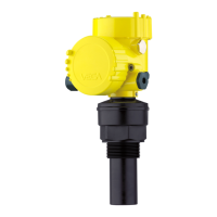
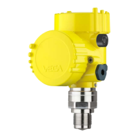
Detailed technical specifications for the LFXG-H gauge.
Examples of industries and uses for the VEGA level gauge.
Explanation of how the gauge measures levels using radiation.
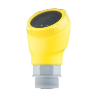
Overview of gauge components: Source holder, detector assembly, communication.
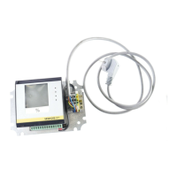
Methods for interacting with the gauge via communicator or PC.
Contact information and procedures for technical support and repairs.
Pre-installation testing of the detector assembly with communication devices.
Factors for optimal installation: temperature, obstructions, cross-talk.
Methods and options for physically mounting the gauge assembly.
Procedures for connecting the gauge's electrical wiring, including plugs.
Procedure for installing a power line switch for CE compliance.
Specifications and connections for the 4-20mA current loop output.
Information on relay specifications and operation.
Details on RS-485 communication setup and cable length.
Methods for connecting and communicating with the gauge.
Installing a switch to manually deactivate process alarms.
Information on power supply requirements and connections for the gauge.
Requirements and procedures for conduit installation, especially in hazardous areas.
Steps involved in bringing the gauge online after installation.
Checklist to prepare for VEGA field service commissioning.
Procedure to adjust the 4-20mA output to a reference.
Steps for measuring current loop output using meters.
Comparison of standard vs. simple calibration methods.
Explanation of calibration principles and data collection.
Method involving collecting intermediate data points for accuracy.
Method requiring only two calibration points, less precise.
Selecting between linear and non-linear response curves for output.
Using non-linear tables for standard calibration accuracy.
Using linear tables for simple calibration.
Procedure to verify the consistency of the gauge's measurements.
Detailed steps for performing standard and simple calibrations.
Adjusting the system to compensate for drifts over time.
Setting up alarms for when standardization is due.
Viewing software calculation steps for level measurement.
Accessing process variables, gauge details, and historical data.
Displaying minimum and maximum parameter values since last reset.
Handling situations with new hardware or corrupted memory.
Modes for troubleshooting: Current Loop, Sensor, Auxiliary Input, Relay, Temperature.
Configuring gauge type (Level/Density) and location (Local/Remote).
System alerts for potential problems via messages and output changes.
Displaying current system status and historical diagnostic information.
Interpreting diagnostic conditions and HART messages.
Checking system status and historical data via diagnostic screens.
Procedures for clearing diagnostic alarms.
Understanding and interpreting various diagnostic alarm messages.
Alarm triggered when detector counts fall below a threshold.
Alarm triggered by process level exceeding high or low setpoints.
Alarm triggered by external radiation sources affecting measurements.
Detecting process changes caused by external x-rays.
Reviewing critical events and internal repairs from diagnostic history.
Field-replaceable circuit boards, test points, jumpers, and LED indicators.
Recommended periodic maintenance schedule.
Logging source wipe and shutter check events in software.
Procedures for replacing field-repairable assemblies/boards.
Information on obtaining replacement parts.
Step-by-step guide for replacing CPU or power supply boards.
Process for returning equipment for service or repair.
| Measuring range | 0.05 m to 200 m |
|---|---|
| Process fitting | Threaded, Flange |
| Output | Bluetooth, USB |
| Measurement Range | 0.05 m to 200 m |
| Operating Temperature | -10°C to 50°C |
| Storage Temperature | -40 ... +80 °C (-40 ... +176 °F) |
| Interface | Bluetooth, USB |