32
5 Connecting to power supply
VEGAPULS 64 • Two-wire 4 … 20 mA/HART
51141-EN-210219
5
1
2
+
( )
(-)
678
4...20mA
3
4
1
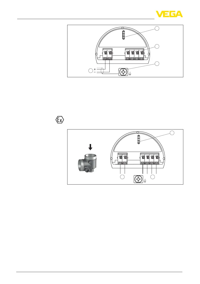
Fig. 29: Electronics and connection compartment - single chamber housing
1 Voltage supply, signal output
2 For display and adjustment module or interface adapter
3 For external display and adjustment unit
4 Ground terminal for connection of the cable screening
5.4 Wiring plan, double chamber housing
The following illustrations apply to the non-Ex as well as to the Ex-ia
version.
567
8
4...20mA
1
2
+
( )
(-)
1 1
Fig. 30: Electronics compartment - double chamber housing
1 Internal connection to the connection compartment
2 For display and adjustment module or interface adapter
Electronics and connec-
tion compartment
Electronics compartment
 Loading...