33
5 Connecting to power supply
VEGAPULS 64 • Two-wire 4 … 20 mA/HART
51141-EN-210219
5
1
2
+
( )
(-)
678
4...20mADisplay
3
4
1
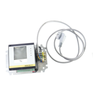
Fig. 31: Connection compartment - double chamber housing
1 Voltage supply, signal output
2 For display and adjustment module or interface adapter
3 For external display and adjustment unit
4 Ground terminal for connection of the cable screening
1
SIM
Status
Send
Off On
1
2
3
+
-
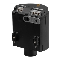
Fig. 32: Connection compartment - Radio module PLICSMOBILE 81
1 Voltage supply
Youcannddetailedinformationforconnectionintheoperating
instructions " PLICSMOBILE".
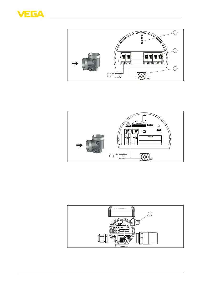
Inthisconguration,anothersensorisconnectedviatheM12x1
plug and also powered via PLICSMOBILE. The sensors must be
operated in HART multidrop.
1
SIM
Status
Send
Off On
1
2
3
+
-
Fig. 33: Sensor with radio module PLICSMOBILE 81 and M12 x 1 plug
1 M12 x 1 plug connector for connection of another sensor
Connection compartment
Connection compart-
ment - Radio module
PLICSMOBILE 81
Connection compart-
ment - Radio module
PLICSMOBILE 81 and
M12 x 1 plug
 Loading...