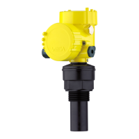
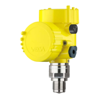
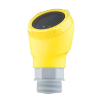
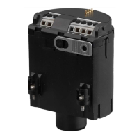
The VEGASON 51K ... 53K series are compact ultrasonic sensors designed for continuous level measurement of liquids and solids, particularly for short measuring distances. They operate on the principle of running time measurement of ultrasonic pulses.
Function Description
The sensors emit focused ultrasonic pulses using piezoceramic high-performance transducers. These pulses reflect off the surface of the medium (solids or liquids). The measuring electronics process the running time and the signal form of the reflected pulses to create a precise picture of the environment. The transducers function as both transmitters and high-sensitivity piezo-microphones (receivers).
The distance between the transducer and the medium is accurately calculated based on the speed of sound and the detected running time of the emitted impulse. This distance is then converted into a level-proportional signal, scaled according to the sensor's parameter adjustment.
The sound velocity is influenced by temperature, so the transducer continuously monitors the ambient temperature to ensure precise level readings even with varying temperatures.
The primary output is a 4-20 mA analogue signal, which is level-proportional. The parameter adjustment for this analogue signal can be individually configured to reflect the desired measuring or adjustment range of the sensor.
Measured Value Indication
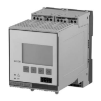
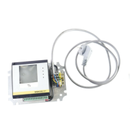
For direct local monitoring, an optional indicating instrument can be mounted directly onto the series 50 ultrasonic sensors. This instrument displays the precise level using both an analogue bar-graph and a digital figure. Additionally, an external indicating instrument, VEGADIS 50, can display the level up to 25 meters away from the sensor. Both integral and external indications operate independently of the 4-20 mA output signal and allow for individual parameter adjustment.
Important Technical Specifications
- Measuring Principle: Ultrasonic (SON)
- Measuring Ranges:
- Liquids: 0.25 - 4 m (Type 51), 0.4 - 7 m (Type 52), 0.6 - 15 m (Type 53)
- Solids: 0.3 - 2 m (Type 51), 0.25 - 3.5 m (Type 52), 0.75 - 7 m (Type 53)
- Output Signal:
- Analogue 4-20 mA (passive, two-wire technology)
- Analogue 4-20 mA (active, four-wire technology)
- Digital output signal (two-wire technology)
- Voltage Supply:
- Two-wire: 24 V DC (16-36 V DC)
- Four-wire: 230 V AC (20-250 V AC), 50/60 Hz; 24 V DC (20-72 V DC)
- Current Consumption: Max. 22.5 mA (two-wire), Max. 140 mA (four-wire)
- Power Consumption: Max. 80 mW, 0.45 VA (two-wire); Max. 1.2 W, 2.50 VA (four-wire)
- Load: Max. 500 Ω (two-wire and four-wire)
- Resolution of 20 mA-signal: 0.025 % of operating range
- Failure of 20 mA-signal: < 0.025 % of operating range
- Ultrasonic Frequency: 70 kHz (Type 51), 55 kHz (Type 52), 34 kHz (Type 53)
- Beam Angle (-3 dB emitted power): 5.5° (Type 51/52), 3° (Type 53)
- Process Connections: G 1½ A, 1½" NPT (Type 51); G 2 A, 2" NPT (Type 52); DN 100 compression flange (Type 53)
- Ambient Temperature:
- Sensor (electronics): -20°C to +60°C
- Process (transducer): -40°C to +80°C (StEx: -20°C to +75°C)
- Storage and transport: -40°C to +80°C
- Max. Vessel Pressure (gauge pressure): 3 bar (Type 51/52), 1 bar (Type 53)
- Protection: IP 67 (sensor), IP 68 (transducer, process)
- Ex-technical data: Ex-approved in Zone 1 (IEC) or Zone 1 (ATEX) classification EEx ia [ia] IIC T6. Intrinsically safe (in conjunction with a safety barrier or separator).
- Temperature Class (permissible ambient temperature on transducer in Ex-areas): T6 (42°C), T5 (58°C), T4 (60°C), T3 (60°C)
- Cable Entry: 2 x M20 x 1.5 (cable diameter 5-9 mm)
Usage Features
- Applications: Level measurement for all liquids and solids (short distances), flow measurement on various flumes, gauge measurement, distance measurement, object monitoring, and conveyor belt monitoring.
- Two-wire Technology (Loop Powered): Supply and output signal on a single two-wire line.
- Rugged and Precise: Unaffected by product properties like density, conductivity, or dielectric constant. Suitable for aggressive substances.
- Adjustment Choices:
- PC with VEGA Visual Operating (VVO) software: Offers a user-friendly interface with pictures, graphics, and process visualizations for quick setup and parameter adjustment. Data can be saved, password-protected, and transferred to other sensors.
- Detachable Adjustment Module MINICOM: A 6-key module with a display that allows for clear-text adjustment. It can be plugged directly into the sensor or an external indicating instrument. Removing the module prevents unauthorized adjustments.
- HART®-Handheld: Series 50 sensors can be adjusted using a HART®-Handheld with standard HART®-menus, without requiring a special Data-Device-Description (DDD).
- Process Connections: Available with G 1½ A, 1½" NPT, G 2 A, 2" NPT threads, and DN 100 compression flanges.
- CE-conformity: Meets EMVG (89/336/EWG) and NSR (73/23/EWG) regulations.
Installation Considerations:
- Measuring Range: Select the instrument based on the required measuring range. The max. filling level depends on the minimum distance of the instrument (0.25 m to 1.4 m) and the installation location.
- Beam Angle and False Echoes: Ultrasonic impulses are focused conically. Objects within the beam angle can cause false echoes. Vertical alignment of the sensor axis to the product surface is recommended, and obstructions within the 100% beam should be avoided.
- Measurement of Liquids:
- Flat Vessel Top: The transducer should protrude at least 60 mm from the flange pipe.
- Dished Tank Ends: Avoid mounting in the center; position at approximately ½ vessel radius from the center to prevent parabolic reflection and amplified false echoes.
- Open Vessels: Use a mounting lever for low-weight sensors.
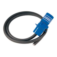
- Pump Shafts and Vessel Openings: For narrow shafts or openings with rough walls, use a socket piece (diameter ≥ 100 mm) or a smooth-walled measuring pipe (diameter ≥ 100 mm) to overcome strong false echoes.
- Measurement of Solids: Mount on a short DIN-socket piece, with the socket axis pointing to the vessel outlet or vertically to the product surface, and keep it very short (< 100 mm).
- Swivelling Holder: For VEGASON 53, a swivelling holder allows directing the sensor to the product surface.
- Mounting Boss: For VEGASON 52, mounting on a boss should ensure the sensor is not too close to the vessel wall.
- Socket Extensions: For longer socket pieces, ensure the transducer protrudes at least 30 mm to avoid strong false echoes. For conical socket extensions, an angle of at least 15-20° is recommended.
- Flow Measurement: Specific guidelines for rectangular and Khafagi-Venturi flumes are provided, emphasizing sensor placement relative to overfall edges, flume center, and liquid surface.
- False Echoes: Vessel protrusions, struts, and intake pipes can cause false echoes. Proper placement, shielding, and false echo storage can mitigate these.
- Installation Errors to Avoid:
- Foam Generation: Can cause faulty measurements. Consider bypass pipes or alternative measurement principles.
- Strong Heat Fluctuations: Can cause measuring errors; use a shield.
- Wrong Directing to the Product: Sensor axis must be vertical to the product surface for optimum results.
- Min. Distance to the Medium Not Maintained: Leads to incorrect measured values.
- Sensor Too Close to the Vessel Wall: Causes false echoes from build-up.
- Flood Basin: Ensure the sensor is mounted high enough to maintain minimum distance even at high water levels, and shield low water edges.
- Inflowing Material: Do not mount in or above the filling stream.
- Strong Product Movements: Use a surge or bypass pipe for reliable measurement in turbulent conditions.
- Socket Piece Too Long: Transducer must protrude at least 30 mm.
Electrical Connection:
- Safety: Ensure the instrument is unpressurized and power supply is off before connecting. Only skilled staff should connect instruments not operating on protective low voltage or DC voltage.
- Connection Cable: Use a standard two or four-wire cable (max. 2.5 mm² cross-section) with an outer diameter of 5-9 mm. Screened cables are recommended to prevent electromagnetic interference. Earth cable screens at both ends only if measurements confirm low earth compensating currents. Cables for intrinsically safe circuits must be marked blue.
- Earth Conductor Terminal: Galvanically isolated on VEGASON 51/52 (shockproof). Galvanically connected to the metal transducer diaphragm on VEGASON 53.
- Ex-protection: Adhere to all necessary regulations and type approvals for hazardous areas (e.g., DIN 0165). Intrinsically safe circuits with multiple active instruments should not be connected.
Maintenance Features
- Adjustment Program VVO: Allows for comprehensive setup, parameter adjustment, and diagnostics. Features include:
- Configuration: Naming measurement loops, defining measurement type (level, distance, gauge).
- Min/Max Adjustment: Setting empty and full levels, with or without medium.
- Conditioning: Defining measurement units, integration time for fluctuating surfaces.
- Linearisation: Pre-adjusted curves (cylindrical, spherical) or user-programmable curves (up to 32 points) for volume calculation.
- Outputs: Adjusting the 4-20 mA signal condition.
- Sensor Optimisation: Defining operating range, measuring conditions (solid/liquid), and managing false echo memory.
- Echo Curve Display: Visualizing the strength and course of ultrasonic echoes to identify and reduce false echoes.
- Simulation: Testing sensor behavior without actual process changes.
- Backup: Saving sensor data to a PC or transferring to other sensors.
- Adjustment Module MINICOM: Provides similar adjustment capabilities to the VVO software via a text display and 6-key field.
- HART®-Handheld: Allows adjustment of main functions using standard HART®-menus. Some advanced functions (e.g., A/D converter scaling, adjustment with medium) may require PC or MINICOM.
- False Echo Storage: Allows the sensor to learn and store false echoes from vessel installations, preventing them from interfering with measurements. This can be created, updated, or deleted.
- Error Codes: The device provides error codes (e.g., E013 for no valid measured value, E017 for adjustment span too small, E036 for no operating sensor program) to assist in troubleshooting.
- Signal-to-Noise (S-N) Value: Indicates the quality of the echo signal, helping to assess measurement reliability. Higher S-N values indicate better measurement.