18
4 Mounting
VEGAPULS 64 • Two-wire 4 … 20 mA/HART
51141-EN-210219
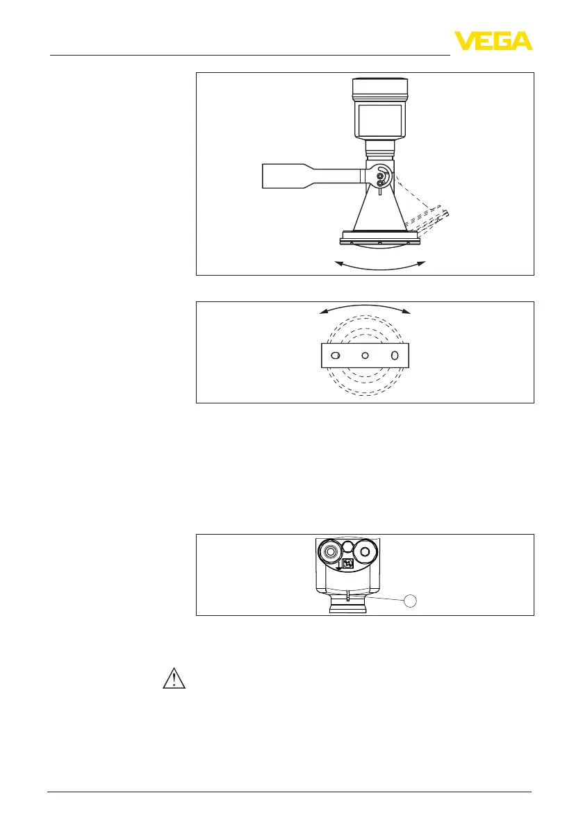
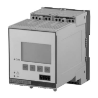
Fig. 9: Adjustment of the angle of inclination
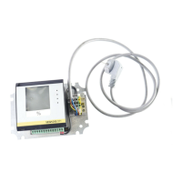
Fig. 10: Turning by fastening in the centre
4.4 Mounting instructions
Radar sensors for level measurement emit electromagnetic waves.
Thepolarizationisthedirectionoftheelectricalcomponentofthese
waves.
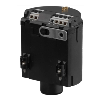
Thepolarizationdirectionismarkedbyanoseonthehousing,see
following drawing:
1
Fig. 11: Position of the polarisation
1 Nose for marking the direction of polarisation
Note:
Whenthehousingisrotated,thedirectionofpolarizationchanges
andhencetheinuenceofthefalseechoonthemeasuredvalue.
Please keep this in mind when mounting or making changes later.
When mounting the device, keep a distance of at least 200 mm
(7.874 in) from the vessel wall. If the device is installed in the center
of dished or round vessel tops, multiple echoes can arise. However,
Polarisation
Installation position