34
5 Connecting to power supply
VEGAPULS 64 • Two-wire 4 … 20 mA/HART
51141-EN-210219
41
2
3
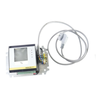
Fig. 34: Top view of the plug connector
Contact pin Terminal electronics mod-
ule additional sensor
Function/Polarity
1 Terminal 1 Power supply/Plus (+)
2 - Do not use
3 Terminal 2 Power supply/Minus (-)
4 - Do not use
1
4 5
6
2
7
3
5
1
2
+
-
678
4...20mA
SIM
Status
Send
Off On
1
23
+-
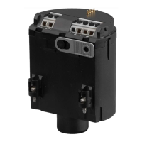
Fig. 35: Connection voltage supply and plics
®
sensor
1 Power supply PLICSMOBILE T81 and connected sensors
2 Sensor connection cable
3 HART sensor from the plics
®
series
4 Brown cable (+) for sensor power supply/HART communication
5 Blue cable (-) for sensor power supply/HART communication
6 Connection of additional HART sensors
7 Unused wires that must be insulated (not present on Ex version)
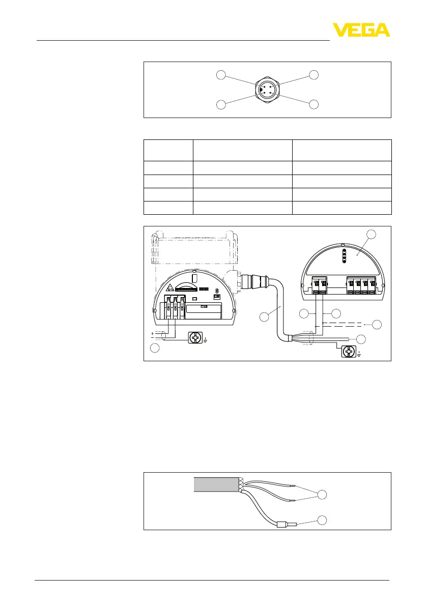
5.5 Wiring plan - version IP66/IP68, 1 bar
1
2
Fig. 36: Wire assignment in permanently connected connection cable
1 Brown (+) and blue (-) to power supply or to the processing system
2 Shielding
Wiring plan - Radio mod-
ule PLICSMOBILE 81 and
M12 x 1 plug
Connection exam-
ple - Radio module
PLICSMOBILE 81 and
plics
®
sensor via VEGA
sensor connection cable
Wire assignment, con-
nection cable
 Loading...