19
4 Mounting
VEGAPULS 64 • Two-wire 4 … 20 mA/HART
51141-EN-210219
these can be suppressed by an appropriate adjustment (see chapter
" Setup").
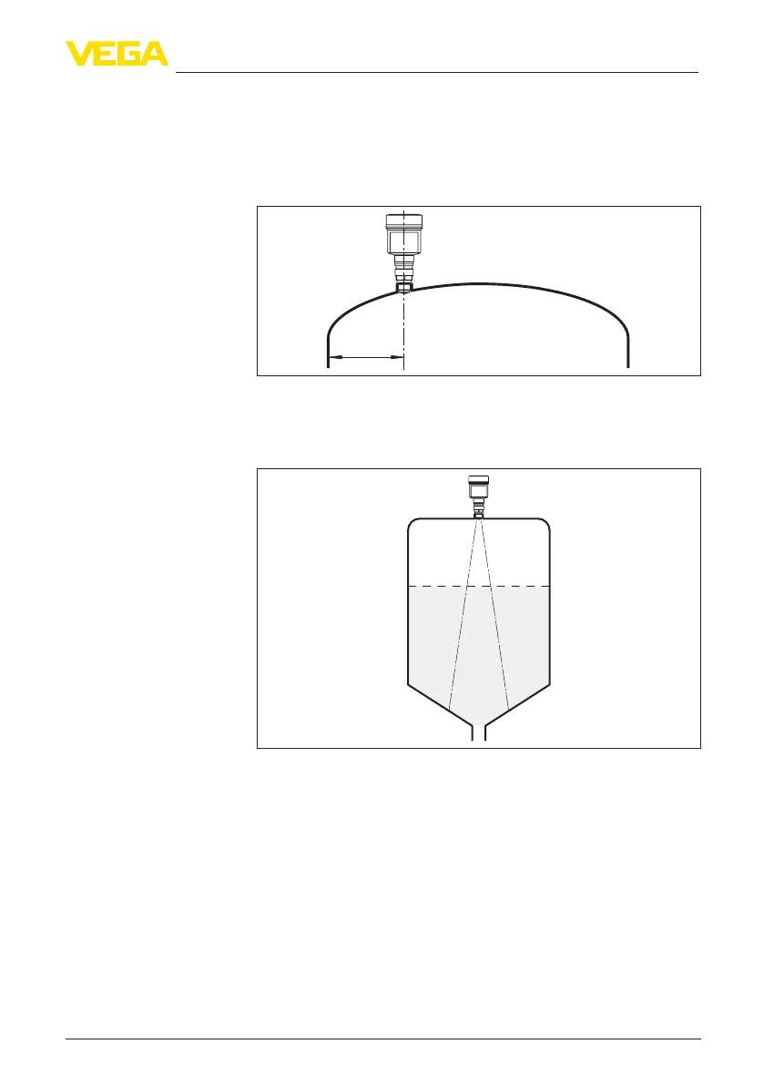
If you cannot maintain this distance, you should carry out a false
signal suppression during setup. This applies particularly if buildup on
the vessel wall is expected. In such cases, we recommend repeating
the false signal suppression at a later date with existing buildup.
> 200 mm
(7.87
")
Fig. 12: Mounting of the radar sensor on round vessel tops
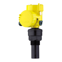
In vessels with conical bottom it can be advantageous to mount the
device in the centre of the vessel, as measurement is then possible
down to the bottom.
Fig. 13: Mounting of the radar sensor on vessels with conical bottom
The measuring range of VEGAPULS 64 begins physically at the end
of the antenna. The min./max. adjustment, however, begins at the
referenceplane.Thereferenceplaneisdierentdependingonthe
sensor version.
•
Plastic horn antenna: The reference plane is the sealing surface
on the lower edge
•
Thread with integrated horn antenna: The reference plane is
the sealing surface at the bottom of the hexagon
•
Flange with encapsulated antenna system: The reference
planeistheloweredgeoftheangeplating
•
Hygienicttings: The reference plane is the highest contact point
betweensensorprocessttingandweldedsocket
Reference plane