20
4 Mounting
VEGAPULS 64 • Two-wire 4 … 20 mA/HART
51141-EN-210219
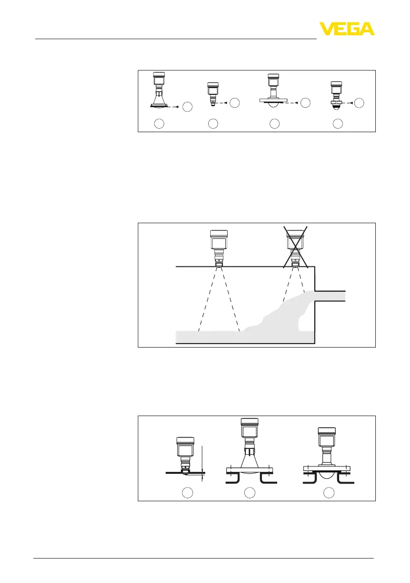
The following graphic shows the position of the reference plane with
dierentsensorversions.
2
1
1
1
1
3
4 5
Fig. 14: Position of the reference plane
1 Reference plane
2 Plastic horn antenna
3 Threaded ttings
4 Flange connections
5 Hygienic ttings
Donotmounttheinstrumentsinorabovethellingstream.Makesure
thatyoudetectthemediumsurface,nottheinowingproduct.
Fig. 15: Mounting of the radar sensor with inowing medium
Fornozzlemounting,thenozzleshouldbeasshortaspossibleand
itsendrounded.Thisreducesfalsereectionsfromthenozzle.
With threaded connection, the antenna end should protrude at least
5mm(0.2in)outofthenozzle.
ca. 5 mm
1 2 3
Fig. 16: Recommended socket mounting with dierent versions of VEGAPULS
64
1 Thread with integrated horn antenna
2 Plastic horn antenna
3 Flange with encapsulated antenna system
Inowingmedium
Nozzle


 To Next Page