75
11 Supplement
VEGAPULS 64 • Two-wire 4 … 20 mA/HART
51141-EN-210219
Variablesinuencingmeasurementaccuracy
9)
Specicationsapplytothedigitalmeasuredvalue
Temperature drift - Digital output < 3 mm/10 K, max. 10 mm
Specicationsapplyalsotothecurrentoutput
Temperature drift - Current output < 0.03 %/10 K or max. 0.3 % relating to the 16.7 mA
span
Deviation in the current output due to
digital/analogue conversion
< 15 µA
Additional deviation through electromagnetic interference
Ʋ According to NAMUR NE 21 < 80 µA
Ʋ According to EN 61326-1 None
Ʋ According to IACS E10 (shipbuilding)/
IEC 60945
< 250 µA
Characteristics and performance data
Measuring frequency W-band(80GHztechnology)
Measuring cycle time approx.
10)
700 ms
Step response time
11)
≤3s
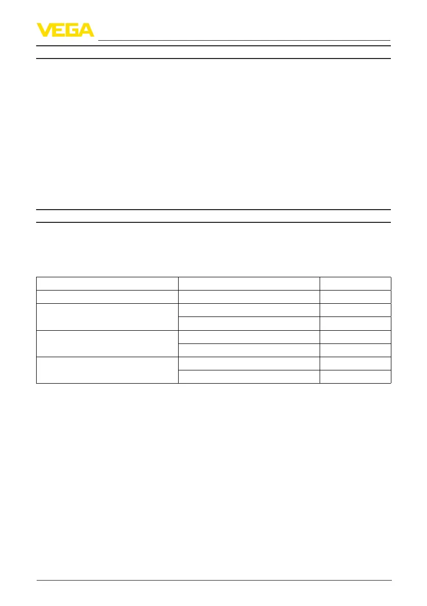
Beam angle
12)
Version Size Beam angle
Plastic horn antenna DN 80 3°
Thread with integrated horn antenna G¾,¾NPT 14°
G1½, 1½ NPT 7°
Flange with encapsulated antenna system ≥DN50,2" 6°
≥DN80,3" 3°
Hygienicttings ≥DN50,2" 6°
≥DN80,3½" 3°
Emitted HF power (depending on the parameter setting)
13)
Ʋ Average spectral transmission power
density
-3dBm/MHzEIRP
Ʋ Max. spectral transmission power
density
+34dBm/50MHzEIRP
Ʋ Max. power density at a distance of
1 m
< 3 µW/cm²
9)
Determination of the temperature drift acc. to the limit point method
10)
With operating voltage U
B
≥24VDC
11)
Timespanafterasuddendistancechangefrom1mto5muntiltheoutputsignalreaches90%ofthenal
valueforthersttime(IEC61298-2).ValidwithoperatingvoltageU
B
≥24VDC
12)
Outsidethespeciedbeamangle,theenergyleveloftheradarsignalis50%(-3dB)less.
13)
EIRP: Equivalent Isotropic Radiated Power.