Menu section, basic adjustment
Level and pressure sensors operate as slaves on the Profibus
PA. To be identified as a bus participant, each sensor must
have a unique address. Each instrument is delivered with
address 126. With this address, it can at first be connected to
an existing bus. However, the address must be changed. This
can be done in this menu item.
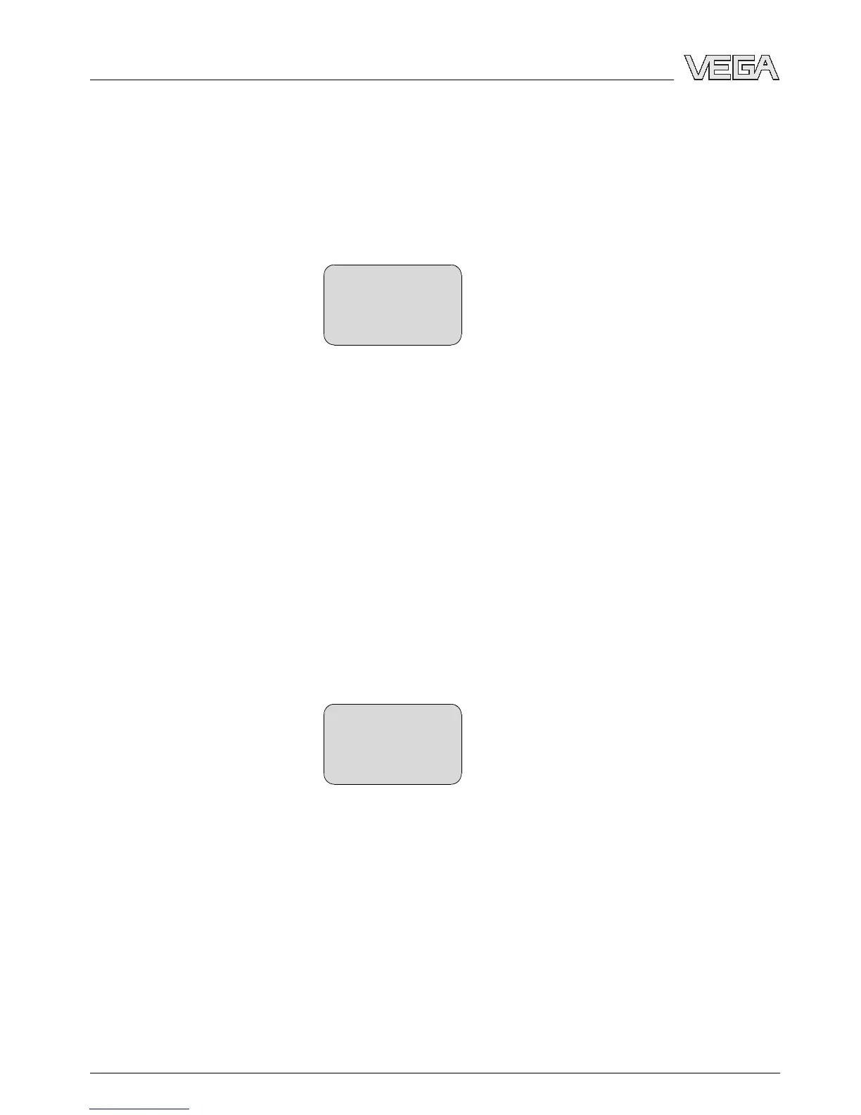
Sensor address
126
The channel is the input selector switch for function block (FB)
of the sensor. Within the function block, additional scalings
(Out-Scale) are carried out. In this menu item, the value fir the
function block is selected:
l SV1 (Secondary Value 1):
- Percent with radar, guided microwave and ultrasonic
sensors
- Pressure or height with pressure transmitters
l SV2 (Secondary Value 2):
- Distance with radar, guided microwave and ultrasonic
sensors
- Percent with pressure transmitters
l PV (Primary Value):
- Linearised percentage value
Channel
PV lin. value
Menu section, display
Radar, guided microwave and ultrasonic sensors deliver the
following measured values:
l SV1 (Secondary Value 1): Percentage value after the
adjustment
l SV2 (Secondary Value 2): Distance value before the
adjustment
l PV (Primary Value): Linearised percentage value
l PA-Out (value after passing the function block): PA output
A pressure transmitter delivers the following measured values:
Sensor address
Channel
Indication
24 Indicating and adjustment module PLICSCOM
Setup
27835-EN-070123