Do you have a question about the Vega plicscom and is the answer not in the manual?
Operations must be carried out only by trained specialist personnel authorized by the operator.
Inappropriate use can give rise to application-specific hazards, e.g. vessel overfill.
Notes Ex-specific safety information for installation and operation in Ex areas.
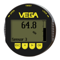
Used for measured value indication, adjustment, and diagnostics for VEGA plics® sensors.
PLICSCOM can be mounted/dismounted anytime without interrupting power supply.
Details the four keys (OK, ->, +, ESC) and their functions for adjustment.
Defines the specific actions of the [OK], [->], [+] and [ESC] keys for navigation and input.
Set integration time (0-999s) to damp process fluctuations.
Selects curve (linear, tank types, user programmable) for non-linear vessel volumes.
Displays min./max. measured values (distance, pressure, temperature).
Displays measurement reliability as dB value (signal strength minus noise).
Displays device status; outputs failure messages (e.g., E013) if a fault is detected.
Simulate user-defined values (percent, current, pressure, distance) for testing signal path.
Reset modified values to basic setting, factory setting, or peak values.
Determine behavior of current output during operation and in case of failure (Output mode, Failure mode).
Activate SIL for sensors suitable for IEC 61508 use, affecting other menu items.
Configure HART mode (Standard, Multidrop) and assign addresses for multidrop operation.
Visual representation of basic adjustment options like Min/Max adjustment, Damping, Linearisation.
Visual representation of basic adjustment for Profibus PA: Sensor address, Min/Max adjustment, Linearisation, Damping.
Visual representation of basic adjustment for Foundation Fieldbus: Unit of measurement, Position correction, Zero, Span, Damping, Linearisation.
The module is maintenance-free when used as directed.
Procedure for returning instrument for repair, including downloading return form and packing.
| Manufacturer | VEGA |
|---|---|
| Category | Control Unit |
| Communication | HART, Profibus PA, Foundation Fieldbus |
| Housing material | Plastic |
| Protection | IP66 |