6
3 Planning
VEGAFLEX 80 series • Two-wire 4 … 20 mA/HART
42960-EN-170410
3 Planning
3.1 Safety function
The sensor generates on its current output a signal between 3.8 mA
and 20.5 mA corresponding to the process variable. This analogue
signal is fed to a connected processing system to monitor the follow-
ing conditions:
•
Exceeding a dened limit value of the process variable
•
Falling below a dened limit value of the process variable
•
Monitoring of a dened range of the process variable
For the design of the safety function, the following aspects must be
taken into account with regard to the tolerances:
•
Due to undetected failures in the range between 3.8 mA and
20.5 mA, an incorrect output signal can be generated which devi-
ates from the real measured value by up to 2 %
•
Increased measurement deviations can occur at the boundaries of
the measuring range (see Technical Data in the operating instruc-
tions)
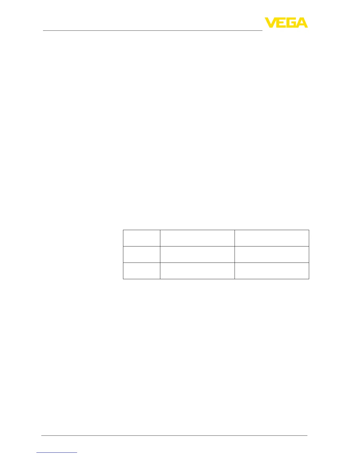
3.2 Safe state
The safe state of the current output depends on the safety function
and the characteristics set on the sensor.
Character-
istics
Monitoring upper limit val-
ue
Monitoring lower limit value
4 … 20 mA Output current ≥ Switching
point
Output current ≤ Switching
point
20 … 4 mA Output current ≤ Switching
point
Output current ≥ Switching
point
Possible fault currents:
•
≤ 3.6 mA ("fail low")
•
> 21 mA ("fail high")
3.3 Prerequisites for operation
•
The measuring system should be used appropriately taking pres-
sure, temperature, density and chemical properties of the medium
into account. The application-specic limits must be observed.
•
The specications according to the operating instructions manual,
particularly the current load on the output circuits, must be kept
within the specied limits
•
Existing communication interfaces (e. g. HART, USB) are not used
for transmission of the safety-relevant measured value
•
The instructions in chapter "Safety-related characteristics", para-
graph "Supplementary information" must be noted
•
All parts of the measuring chain must correspond to the planned
"Safety Integrity Level (SIL)"
Safety function
Safety toler
ance
Safe state
Fault signals in case of
malfunction
Instructions and restric-
tions
 Loading...