8
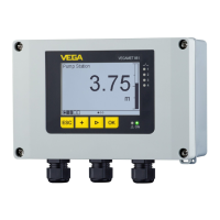
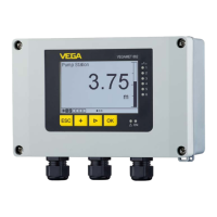
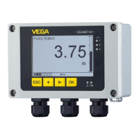
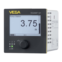
VEGAMET 841, 842, 861, 862
61274-EN-200723
Intrinsicallysafecircuit
Supplyandsignalcircuit:
4 … 20 mA-Sensor 1: Terminals 1[+], 2[-]
In addition only VEGAMET 862:
4 … 20 mA sensor 2: Terminals 4[+], 5[-]
In type of protection intrinsic safety Ex ia IIC, IIB/IIIC.
For connection to a certied, intrinsically safe circuit.
U
o
≤ 23.3 V DC
I
o
≤ 111.3 mA
P
o
≤ 648.4 mW
Characteristics: linear
C
i
negligibly small
L
i
negligibly small
The maximum values given in the table can be used as concentrat-
ed capacitances and concentrated inductances.
The values for IIC and IIB are also permissible for dust explosive
areas.
Ex ia IIC IIB, IIIC IIA
Permissible external inductance L
o
0.2 mH 0.5 mH 0.5 mH 2 mH 10 mH
Permissible external capacitance C
o
120 nF 88 nF 580 nF 470 nF 760 nF
The intrinsically safe circuits of VEGAMET 841, 842, 861, 862 are galvanically separated from
ground.
The intrinsically safe circuits of the VEGAMET 841, 842, 861, 862 are reliably separated from the
non-intrinsically safe circuit up to a peak value of 375 V.
The maximum voltage on the non-intrinsically safe circuits must not exceed 253 Vrms in the event of
a fault.
10 Mechanicaldata
The following mechanical data are valid for all housing and electronics versions.
Mechanicaldata
Protection (IEC/EN 60529) TYPE 4X, IP66/IP67
Connection cross-section:
0.25 … 2.5 mm
2
Overvoltage category II
Pollution degree 4
11 Thermaldata
Permissibleambienttemperatures
Permissible ambient temperature at the installation lo-
cation of an instrument
Ambienttemperature(Ta)
as associated apparatus for installation in zone 2 -40 … +50 °C (-40 … +122 °F)
12 Installation
The controllers VEGAMET 841, 842, 861, 862 as associated equipment for installation in zone 2/Div
 Loading...