Do you have a question about the Vega VEGATOR 636 Ex and is the answer not in the manual?
Explains the purpose of the operating instructions manual for mounting, connection, and setup.
Identifies the manual's audience as trained specialist personnel for proper use.
Details the meaning of symbols like information, caution, warning, danger, Ex, lists, and actions.
States that all operations must be performed by trained specialist personnel authorized by the plant operator.
Defines the instrument's function and stresses proper usage for operational reliability and warranty.
Warns that incorrect use can lead to hazards, such as vessel overfill or damage.
Emphasizes strict adherence to regulations, guidelines, and operating the instrument in a technically flawless condition.
Confirms the device fulfills EC guidelines and bears the CE mark as proof of successful testing.
Highlights the importance of Ex-specific safety information for installation and operation in Ex areas.
Encourages adherence to environmental instructions for protection and recycling, referencing specific chapters.
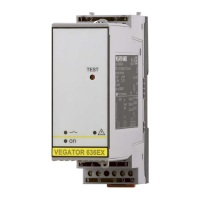
Lists the items included in the scope of delivery and the constituent parts of the VEGATOR 636 Ex.
Explains how the instrument conditions signals from level switches and its functional principle.
Describes how to preset switching delay and mode using a DIL switch block and test key.
Details packaging standards, transport guidelines, inspection, and storage conditions.
Covers installation place, transparent cover removal, and housing IP 65 for moisture-protected mounting.
Details mounting on carrier rails, connection of operating voltage, and safety warnings for bridges.
Explains the mandatory attachment of the Ex separating chamber for Ex versions for safe operation.
Describes mechanical coding and the use of coded pins to prevent interchanging instrument types.
Covers safety instructions, power supply options, connection cable selection, and grounding for sensors.
Provides a step-by-step guide for physically connecting the instrument to the carrier rail and power.
Illustrates the wiring connections for sensors, outputs, and operating voltage for the VEGATOR 636 Ex.
Details the display and adjustment elements, including test key, control lamps, and terminal sockets.
Explains the function of the green, red, and yellow control lamps indicating operation, fault, and status.
Describes the six-position DIL switch block for setting mode, switch-off delay, switch-on delay, and switching delays.
Outlines the continuous monitoring of the measuring system for various fault conditions.
Explains the integrated test key function for checking switching outputs and signal processing.
Details the steps for conducting a function test and evaluating the results based on switching conditions.
Provides an overview of switching conditions based on set mode and level, showing sensor current and output states.
States that no special maintenance is required for proper operation.
Guides users on checking input/output signals and troubleshooting common faults with causes and rectification steps.
Continues troubleshooting steps for specific fault conditions, including current values and lamp indicators.
Provides instructions for returning instruments for repair, including downloading forms and packaging requirements.
Refers to mounting and connection chapters for reverse steps to dismount the instrument.
Advises on recycling materials and proper disposal of the instrument according to WEEE directive and national laws.
Lists detailed technical specifications for general data, voltage supply, sensor input, relay output, and transistor output.
Details the adjustment elements like DIL switch block, test key, and control lamps.
Specifies permissible ambient temperature and storage/transport temperature ranges.
Covers protection rating, overvoltage category, protection class, and electrical separating measures.
Explains the instrument's suitability for safety-instrumented systems and the availability of SIL qualification documentation.
Mentions that approval documents may contain different technical data and should be noted.
Provides dimensional drawings and measurements of the VEGATOR 636 Ex and its mounting components.
| Brand | Vega |
|---|---|
| Model | VEGATOR 636 Ex |
| Category | Industrial Equipment |
| Language | English |