Do you have a question about the Velleman K1803 and is the answer not in the manual?
Technical details including power supply, output impedance, frequency range, and input signal limits.
Lists necessary tools like soldering iron, pliers, and cutters for kit assembly.
Guidelines for careful construction, including reading instructions and verifying component values.
Instructions on proper soldering, lead trimming, component handling, and tape usage.
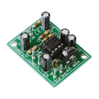
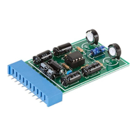
Guidance for installing resistors (R1-R7) according to their values and PCB placement.
Instructions for correctly positioning and installing the 8-pin IC socket (IC1).
Specific advice for mounting vertical resistors on the printed circuit board.
Details on how to install the various PCB pins for input, output, and power connections.
Important notes on the polarity and correct placement of electrolytic capacitors (C1-C5).
Guidance for mounting the trim potentiometer (RV1) with its specified resistance value.
Precise steps for mounting the LM358 IC (IC1), emphasizing correct orientation.
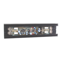
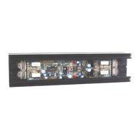
Instructions for connecting power supply and audio signals to the preamplifier module.
Advice on using screened wire for input and output to prevent interference.
Explanation of how the trimmer RV1 controls the output signal level.
Detailed circuit diagram showing all components and their interconnections.
Visual guide to the printed circuit board layout, showing component placement.
| Impedance | 1000 Ω |
|---|---|
| Sensitivity | 40 dB |
| Frequency range | 20 - 20000 Hz |
| Connectivity technology | Wired |
| Product color | Green |
| Power requirements | 10-30VDC, 10mA |
| Manual | Yes |
| Depth | 44 mm |
|---|---|
| Width | 30 mm |