EasyManua.ls Logo

Velleman K4040 User Manual

Velleman K4040
29 pages
To Next Page IconTo Next Page
Page #1 background imageLoading...
Page #1 background image
Total solder points: 700
Difficulty level:
beginner 1o 2o 3o 4o 5þ advanced
ILLUSTRATED PARTLIST H4040IP-ED1
K4040
STEREO VALVE POWER AMPLIFIER
Pure valve sound with high quality EL34 valves
High quality black and chrome housing
Chrome valve socket covers
Easy bias adjustment with LED indication
Removable bottom for easy access and service
High quality capacitors and components
Gold plated input and speaker terminals
Standby function
Soft start circuit for power transformer
Specifications
2 x 90Wrms in 4 or 8
Up to 2 x 15Wrms full class A
Bandwidth: 8Hz to 80KHz (-3dB/1W)
Harmonic distortion: 0.1% @ 1W/1KHz
Signal to noise ratio: >105dB (A weighted)
Input sensitivity: 1Vrms
115VAC or 230VAC / 500VA max.
modifications reserved
stereo power amplifier
4040

Other manuals for Velleman K4040

Question and Answer IconNeed help?

Do you have a question about the Velleman K4040 and is the answer not in the manual?

Velleman K4040 Specifications

General IconGeneral
Impedance4 - 8 Ohms
Frequency Response20 Hz - 20 kHz
Total Harmonic Distortion< 1%
Signal-to-Noise Ratio> 90 dB
Input Sensitivity300 mV
Power Supply230 V AC
TypeValve

Summary

Stereo Valve Power Amplifier Introduction

Technical Data and Specifications

Tools and Procedures

Lists required tools and outlines basic soldering and mounting procedures.

Initial Component Installation

Capacitors, Connectors, and Wiring

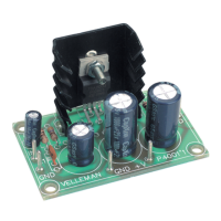
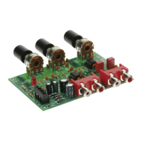
Instructions for mounting capacitors, RCA connectors, and connecting shielded wire.

Valve Socket Mounting

Jumpers, Diodes, and Resistors Installation

Jumper Configuration and Tips

Details jumper settings for voltage selection and wiring tips.

Diode and Resistor Installation

Instructions for installing diodes and 1W resistors.

ICs, Relays, Trimmers, and Transistors Installation

IC Socket and Reed Relay Installation

Instructions for mounting IC sockets and reed relays, noting notch positions.

Resistor Trimmer and Transistor Installation

Guide for installing vertical resistor trimmers and transistors.

Valve Wiring and Cabinet Assembly

6.3V Valve Wiring

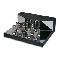
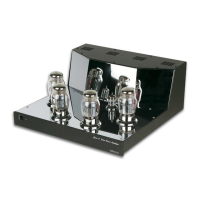
Procedure for wiring the 8 tube sockets with 6.3V connections.

Assembly into the Cabinet

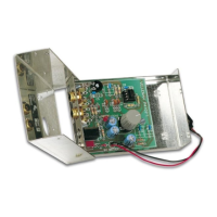
Instructions for mounting cage nuts and preparing the unit for cabinet assembly.

Setting Up and Adjustment

Standby Current Adjustment

Procedure for adjusting the standby or bias current for each tube.

Left-Hand Channel Adjustment

Steps to adjust the bias for the left-hand channel tubes using DIP switches and potentiometers.

Right-Hand Channel Adjustment and Test

Right-Hand Channel Adjustment

Steps to adjust the bias for the right-hand channel tubes.

Amplifier Testing

Procedure for connecting loudspeakers and checking for hum.

Usage, Warnings, and Troubleshooting

General Warnings

Important safety warnings regarding heat, voltage, and handling.

Trouble Shooting

Common problems and their solutions, including crackling and buzzing.

Related product manuals