Do you have a question about the Velleman K4102 and is the answer not in the manual?
Lists key features like sound adjustment, adjustable input sensitivity, low noise, and housing inclusion.
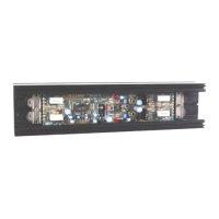
Details headphone output, power supply, and physical dimensions of the preamplifier.
Lists necessary tools such as soldering iron, cutters, pliers, and screwdrivers for kit building.
Provides crucial tips for successful assembly, including following instructions, order, and checking component values.
Explains proper soldering techniques, joint appearance, and trimming excess leads for quality connections.
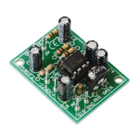
Identifies Zener diode, 1/4W resistors, ceramic, and electrolytic capacitors with their values and codes.
Covers the IC socket, resistor trimmers (RV1, RV2), and the switch (SW1) for the project.
Describes RCA connectors, headphones connector, and the LED indicator.
Details the integrated circuit (NE5532A) and the battery snap connection.
Instructions for attaching the PCB to the housing using spacers and bolts, and installing the tone control shaft and knob.
Describes how to connect the battery and close the housing cover after all internal components are assembled.
Instructions for connecting the battery, switching on, and checking the LED indicator for proper operation.
Guides on testing headphone output with hum and adjusting sensitivity and tone controls with a guitar.
Advice on connecting the output to stereo systems and a caution regarding volume levels to prevent speaker damage.
Presents the complete circuit diagram showing components, connections, and signal flow for the guitar preamplifier.
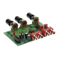
Illustrates the physical layout of components on the Printed Circuit Board for correct placement during assembly.
| Frequency Response | 20Hz - 20kHz |
|---|---|
| Type | Stereo amplifier |
| Load Impedance | 4 ohms |
| Power Supply | 12V DC |
| Output Power | 2 x 50W music power |