Do you have a question about the Velleman K8010 and is the answer not in the manual?
Lists essential tools like soldering iron, solder, cutters, and pliers required for the build.
Provides guidelines on skill matching, following instructions, correct assembly order, and checking component values.
Offers tips on proper soldering techniques, including component placement, joint appearance, and lead trimming.
Instructions for mounting jumper wires, noting special requirements for current handling for certain jumpers.
Guides the selection and mounting of jumpers to configure the unit for different AC mains voltage inputs.
Lists diodes (1N4148, 1N4007, 1N5408) and emphasizes the critical need to check their polarity during installation.
Identifies Zener diodes ZD1 and ZD2 (3V9) and reiterates the importance of checking polarity.
Details a comprehensive list of 1/4W and 1/2W resistors (R1-R54) with their values and color codes.
Lists various 1W resistors (R55-R72) by value and color code for proper installation.
Specifies different LEDs (LD1-LD13) by type, color, size, and function, stressing the importance of polarity checks.
Provides instructions for installing IC sockets, specifically IC1 (18P), highlighting the correct orientation of the notch.
Instructions for mounting reed relays (RY1) and ensuring correct notch positioning for proper function.
Details the installation of DIP switches (SW2), emphasizing correct pin-to-switch correspondence.
Guides the mounting of trimmer potentiometers (RV1-RV5) for vertical and horizontal types, including resistance values.
Lists transistors (T1-T4) by type (BC516, BC547C) and displays their pin configurations for correct mounting.
Lists 5W resistors (R73-R75) and notes that one 15 Ohm resistor is included for later use.
Instructions for mounting PCB blade terminals (SK1-SK10, SK21-SK22), stressing straight mounting and good solder joints.
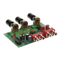
Provides guidance on mounting cinch/RCA connectors (SK11) straight and square to the PCB for optimal connection.
Details mounting instructions for PCB terminal blocks (SK12-SK17), with wire inputs oriented towards the PCB edge.
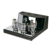
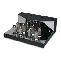
Instructions for mounting valve sockets (V5, V6) directly onto the PCB, showing their pin arrangements for correct placement.
Guidance on mounting switches (SW1), ensuring squareness to the PCB and soldering the supporting metalwork.
Lists various capacitors (C1-C13) with their values, voltage ratings, and codes, emphasizing the need to check voltage ratings.
Information on mounting power relays (RY2-RY4) and their correspondence to PCB footprints.
Lists electrolytic capacitors (C14-C27) with values and voltage ratings, highlighting the importance of checking polarity.
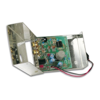
Instructions for mounting the transformer (TRAFO1) and details its connections.
Lists snap-in type electrolytic capacitors (C28-C31), noting their resistance to incorrect mounting.
Provides instructions for inserting the IC (IC1: LM3914), stressing the critical step of checking the notch position.
Detailed wiring diagram for the four valve sockets (V1-V4) using brown wire, with checks for polarity and shorts.
Specific instructions for mounting a bicolor LED (LD2), including polarity and connection details for proper function.
Detailed steps for calibrating bias current for each valve using dipswitches and trim potentiometers, requiring utmost attention.