Do you have a question about the Velleman K4001 and is the answer not in the manual?
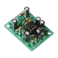
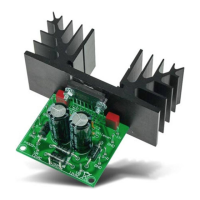
Details about the TDA2003 IC amplifier, its protection features, and power supply connection.
Technical specs including output power, distortion, frequency response, sensitivity, S/N ratio, supply, and dimensions.
Lists essential tools for assembly and provides general guidelines for successful project execution.
Details on correct soldering, including component mounting, joint quality, and trimming excess leads.
Guidance on identifying, placing, and installing resistors, capacitors, and the IC on the PCB.
Example of a mains supply connection and using batteries to power the circuit.
Instructions for connecting a 47K logarithmic potentiometer for volume adjustment.
Diagram showing how to connect a speaker, potentiometer, and power supply to the amplifier board.
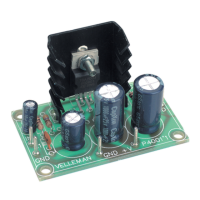
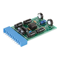
Visual representation of component placement on the printed circuit board.
Schematic representation of the electronic components and their interconnections.
| Impedance | 150000 Ω |
|---|---|
| Sensitivity | 86 dB |
| Amplifier class | - |
| Frequency range | 20 - 20000 Hz |
| RMS rated power | 3.5 W |
| Audio output channels | - channels |
| Peak power per channel | - W |
| Total Harmonic Distortion (THD) | 0.05 % |
| RMS power output per channel (8 Ohm) | 2 W |
| Output power | 7 W |
| Power requirements | 15VDC, 0.5A |
| Connectivity technology | Wired |
| Product color | Green |
| Handheld remote control | No |
| Manual | Yes |
| Maximum current | 0.5 A |
| DC input voltage | 8 - 18 V |
| Depth | 35 mm |
|---|---|
| Width | 55 mm |