__________________________________________________________________________________________________________________________________________________________
7
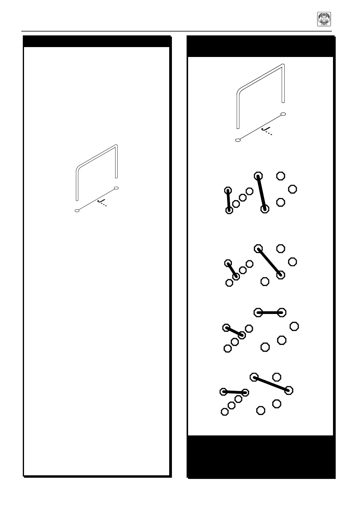
2. JUMPERS
q J1 (mount 2 wires)
q J2 (mount 2 wires)
q J3 (mount 2 wires)
q J4 (mount 2 wires)
q J5 (mount 2 wires)
q J6 (mount 2 wires)
q J7
q J8
q J9
q J10
q J11
q J12
q J13
q J14
q J15
q J16
q J17
q J18
q J19
q J20
q J21
q J22
q J23
q J24
q J25
q J26
3. JUMPERS FOR VOLTAGE
SELECTION
MAINS VOLTAGE SELECTION:
For 100V mains input, mount:
A
A
For 120V mains input, mount:
B
B
For 230V mains input, mount:
C
C
For 240V mains input, mount:
D D
REMARK:
Strike out the NOT used mains voltage indica-
tion at the back of the housing !! e.g. cross out
with a permanent black marker
4. DIODES (Check the polarity!)
Note that from J1 to J6, two jumper leads have
to be mounted in the same hole.
TIP
In order to get nice straight wiring, without too
much folding and measuring, follow these
hints:
• Mount the lead on the PCB as it is.
• Solder 1 end of the lead.
• Then carefully pull on the free end of the
lead until it is straight.
• Now solder the other end.