EasyManua.ls Logo

Velleman K4306 User Manual

Velleman K4306
32 pages
Go to English
To Next Page IconTo Next Page
Page #1 background imageLoading...
Page #1 background image
H4306B-1
S
W
-
+
1
5
V
D
C
A
d
a
p
t
e
r
1
N
4
0
0
7
G
N
D
I
O
G
N
D
C
1
2
2
0
µ
/
3
5
G
N
D
C
2
1
0
0
n
G
N
D
G
N
D
D
2
1
N
4
1
4
8
D
3
1
N
4
1
4
8
C
3
1
0
0
n
G
N
D
G
N
D
C
4
1
0
0
n
G
N
D
I
O
GN
D
1
6
2
7
3
8
4
9
5
S
K
2
S
U
B
D
9
-P
O
LE
F
EM
A
L
E
T
1
B
C
5
4
7
R
1
1
5
K
G
N
D
D
4
1
N
4
1
4
8
G
N
D
R
3
4
K
7
+
5
V
R
4
1
K
R
2
2
2
0
K
G
N
D
R
B
6
R
5
1
5
K
T
2
B
C
5
4
7
R
6
2
2
0
K
D
5
1
N
4
1
4
8
G
N
D
G
N
D
G
N
D
R
7
4
K
7
+
5
V
R
8
1
K
G
N
D
T
3
B
C
5
5
7
+
5
V
R
9
4
K
7
R
1
0
3
K
3
R
1
1
4
K
7
D
6
1
N
4
1
4
8
R
1
2
3
3
0
T
4
B
C
5
4
7
D
7
1
N
4
1
4
8
+
V
P
P
M
R
1
6
3
9
0
L
D
7
L
E
D
3
G
G
N
D
R
1
3
1
5
K
R
1
4
3
K
3
K4306
2 x 15 LED stereo VU-meter ................................... 3
VU - mètre stéréo à 2 x 15 DEL ............................. 7
2 x 15 LED stereo-VU-meter ................................... 7
NL
FR
DE
Question and Answer IconNeed help?

Do you have a question about the Velleman K4306 and is the answer not in the manual?

Velleman K4306 Specifications

General IconGeneral
CategoryMeasuring Instruments
ModelK4306
Diode TestYes
Transistor TestYes
Continuity TestYes

Summary

Features and Specifications

Assembly Steps

Jumper Wires

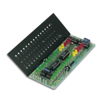
Install jumper wires as per the diagram for BAR or DOT readout selection.

Diodes Polarity

Install diodes, paying close attention to their polarity and orientation.

Zener Diode Polarity

Install the Zener diode, ensuring correct polarity and orientation.

Metal Film Resistors

Install metal film resistors according to the schematic and markings.

Resistors

Install standard resistors, checking values and orientation.

IC Sockets

Install IC sockets, ensuring the notch orientation is correct.

Capacitors

Install ceramic capacitors, noting their values.

Trim Potentiometers

Install the trim potentiometers (potentiometers).

Electrolytic Capacitors Polarity

Install electrolytic capacitors, observing correct polarity.

1W Resistors

Install 1 Watt resistors, matching values to the schematic.

LEDs Polarity

Install LEDs, ensuring correct polarity and orientation for illumination.

ICs Polarity

Install ICs, aligning the notch or pin 1 correctly.

Enclosure Assembly

Signal Connection

Speaker Output Connection

Car Radio Connection

PCB Layout

Circuit Diagram

Related product manuals