15
4. CONTROLS (CONT’D)
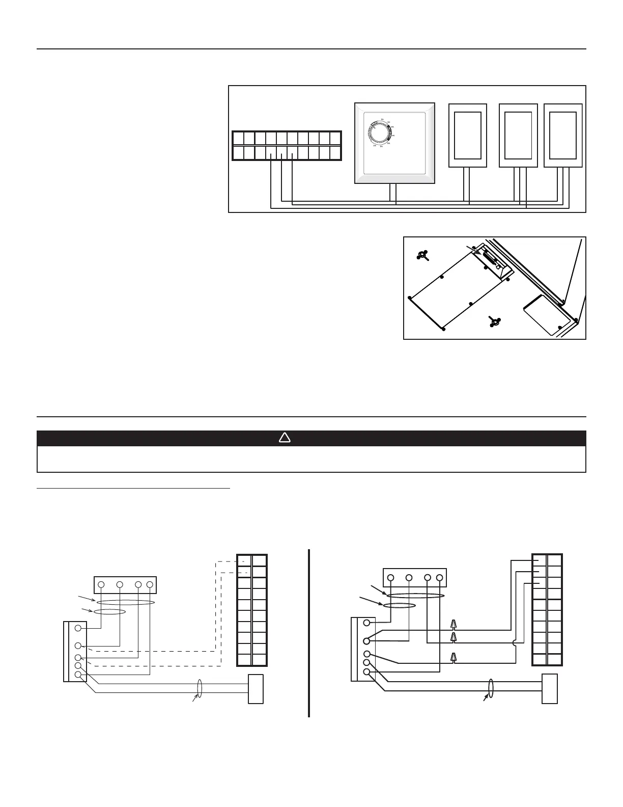
4.6 ELECTRICAL CONNECTION TO OPTIONAL AUXILIARY CONTROLS (ALL UNITS)
NO C NC I OC OL Y R G B
PUSH-BUTTON TIMERS
60-MINUTE
CRANK TIMER
DEHUMIDISTAT
VE0296A
NOTE: If an optional auxiliary control is
activated and then, the Dehumidistat
is being activated, the Dehumidistat
will override the auxiliary control
commands.
Once the control(s) connections have been made, insert the terminal connector In the
recessed side of the electrical compartment.
NOTE: For information about the operation of the wall controls, refer to the user guide.
VD0206
BOTTOM OF THE UNIT
TERMINAL
CONNECTOR
5. ELECTRICAL CONNECTION TO THE FURNACE
WARNING
Never connect a 120-volt AC circuit to the terminals of the furnace interlock (standard wiring). Only use the low
voltage class 2 circuit of the furnace blower control.
For a furnace connected to a cooling system:
On some older thermostats, energizing the “R” and “G” terminals at the furnace has the effect of energizing “Y” at the thermostat and
thereby turning on the cooling system. If you identify this type of thermostat, you must use the ALTERNATE FURNACE INTERLOCK WIRING.
STANDARD FURNACE INTERLOCK WIRING ALTERNATE FURNACE INTERLOCK WIRING
W R G
Y
W
R
G
C
Y
UNIT TERMINAL CONNECTOR
THERMOSTAT
TERMINALS
FOUR
WIRES
TWO WIRES
heating only
FURNACE
24-VOLT
TERMINAL BLOCK
TWO WIRES
COOLING SYSTEM
NO C NC I OC OL Y R G B
W R G Y
W
R
Y
R
G
Y
C
THERMOSTAT
TERMINAL
4 WIRES
2 WIRES
heating only
wiring
nuts
FURNACE
24-VOLT
TERMINAL BLOCK
2 WIRES
COOLING SYSTEM
NO
NC
C
UNIT TERMINAL CONNECTOR
NO C NC I OC OL Y R G B
VE0108A