5
These following curves illustrate the air volume through the units for a typical
installation. A typical installation is close to an exterior wall, in order to shorten
the insulated duct length. On the warm air side (between the unit and the
furnace), use steel rigid ducts. It is strongly recommended to minimize the
number of elbows to ease air flow. See Section 3.0 and 4.0 for more details.
2.2 PERFORMANCE CHART
0.00
0.10
0.20
0.30
5040 60 80 100 1209070
Flows (cfm)
Pressure (in. water gauge)
VG0031A
Stale air Fresh air
0.05
0.15
0.25
110
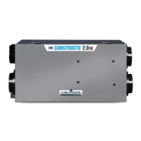
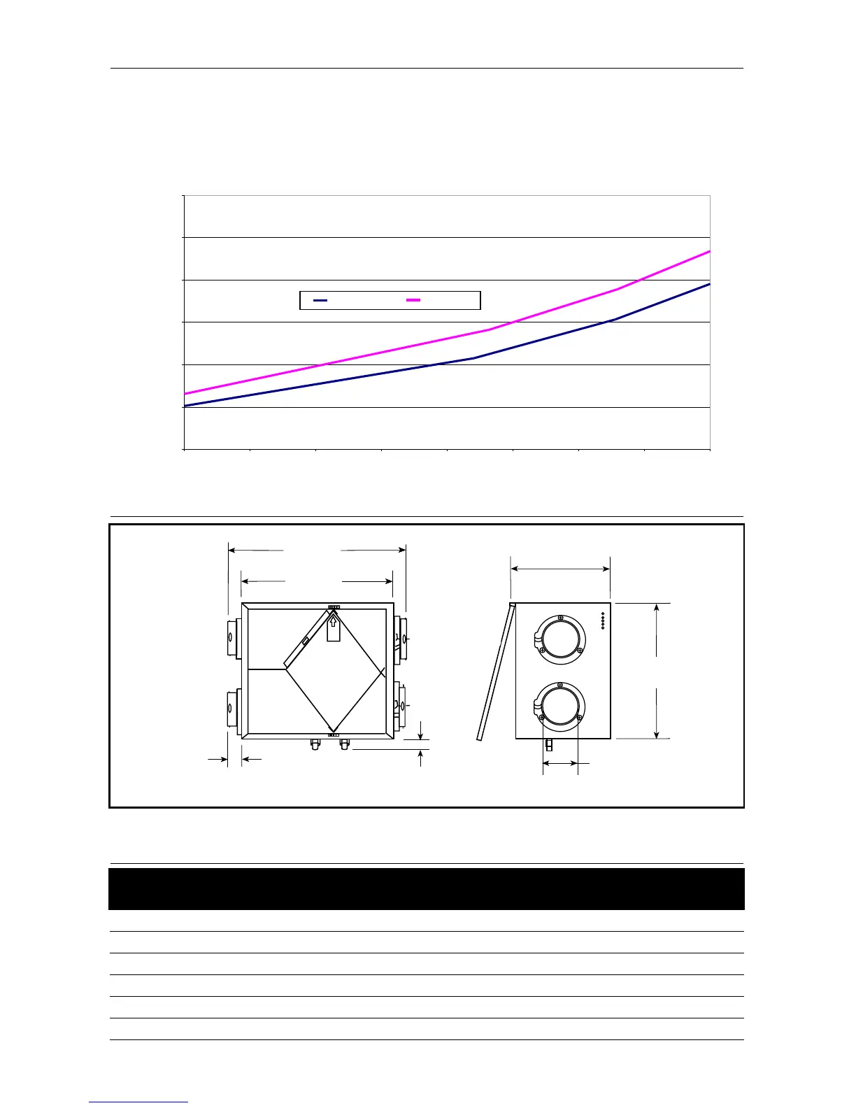
2.3 DIMENSIONS
VK0028
22.562”
(573 mm)
27.250”
(692 mm)
1.500’’
(38 mm)
2.225”
(57 mm)
20.000”
(508 mm)
14.500”
(368 mm)
6.000”
(152 mm)
NOTE: Typical illustration; dimensions are the same for all models.
* For models FAE115M, uFAE115M and vFAE115M only.
Weight 35.3 lbs (16 kg) 40.6 lbs (18.4 kg)
Port diameter 6 inches (152 mm) 6 inches (152 mm)
Drain diameter 1/2 inch (12 mm) 1/2 inch (12 mm)
Installation Chains (provided with the unit) Chains (provided with the unit)
Electrical supply* 24 Volts, AC 24 Volts, AC
Power consumption* 6 Watts 6 Watts
Models
FAE115 & FAE115M
uFAE115 & uFAE115M
vFAE115 & vFAE115M
2.4 SPECIFICATIONS