SERVICING & MAINTENANCE
WARNING: THE FAN AND ANCILLARY CONTROL EQUIPMENT MUST BE
ISOLATED FROM THE POWER SUPPLY DURING MAINTENANCE.
1. Individual faulty parts should not be replaced due to complexity of assembly. Only the full scroll
assembly is replaceable.
2. To remove the scroll assembly, isolate the power, then use a coin or similar to depress the cover
retention clips and remove the cover.
3. Disconnect and remove the power supply and signal leads.
4. Remove the scroll assembly by unscrewing the two screws and unclipping the clips in the opposite
two corners and lift the scroll assembly out of the housing.
5. The fan has sealed for life bearings, which do not require lubrication. Expected service life is at least
45,000 hours continuous running.
6. Upon reassembly, check all fixings are tight and secure.
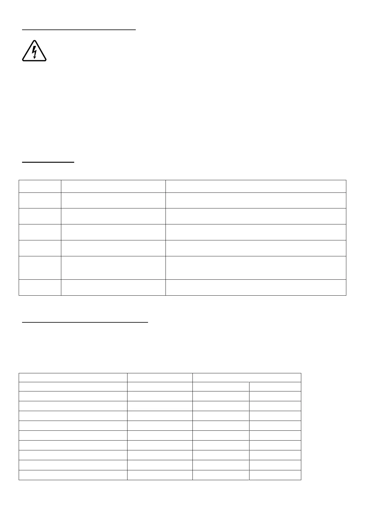
FAULT CODES
If the MEV unit detects a fault it will display an error message on the HMI display:
Control fault – Unit failed startup
check
Turn the power off and on again.
Check that the impellor has free movement.
Check internal motor wiring.
Humidity/Temp sensor Fault –
No value – internal sensor
Contact tech support, scroll part.
CO
2
sensor Fault – No value –
internal sensor
Check the internal wiring to the sensor
Temp or Humidity sensor
connected via RF/RS485 is
offline/Lost
Check that the sensor is turned on.
Re-pair the sensor to the unit, see page 10.
CO
2
sensor connected via
RF/RS485 is offline/Lost
Check that the sensor is turned on.
Re-pair the sensor to the unit, see page 10.
If the a fault persists, contact your local technical support, see the back cover of this manual for details.
SPARE PARTS AND ACCESSORIES
For spare parts and accessories, please contact your local agent, details provided on the final page of this
manual.
Compatible accessories
Sensor/Controller Name / Function
Alarm interface module (230V)
External Temp/RH (battery)
Speed Switch 4 way (Battery)
Speed Switch 4 way (230V)