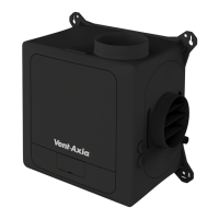
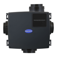
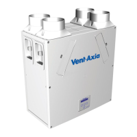
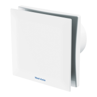
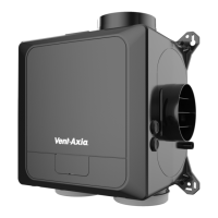
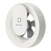
This document describes the Lo-Carbon MVDC & Sentinel Multivent Range of ventilation systems, including installation and wiring instructions. These units are designed for simultaneous extract ventilation in multiple areas such as bathrooms, kitchens, and toilets, and are suitable for continuous 24-hour use. They utilize highly efficient backward-curved centrifugal motor impeller sets.
Function Description
The MVDC & Sentinel Multivent units offer either 3 or 4 settable speeds, depending on the model, and can be configured to adjust speed based on a wide range of sensor or control inputs. The units are precisely programmable to determine their response to changes in sensor values or signal input status. They typically operate at a "Normal" flowrate until a sensor or input change triggers a speed adjustment. For Switched Live and Digital inputs, a step change in speed occurs. For Analogue, Humidity, and CO2 sensors, the unit can be programmed for a proportional response to changing conditions.
Usage Features
- Speed Control: Multiple settable speeds (Low, Normal, Boost, Purge) allow for flexible ventilation control.
- Input Options: Supports various inputs including Switched Live (LS1, LS2), Analogue (0-10V), Digital, Humidity Sensor, CO2 Sensor, and Wireless Receiver.
- Programmable Response: Units can be programmed to respond to sensor and input changes, with options for step changes or proportional responses.
- Comfort Mode: When enabled, this mode modifies the unit's behavior for LS inputs. For example, if an LS input is active for less than 5 minutes, there is no action. If active for 5-20 minutes, the fan runs at a user-selected speed for the duration of LS presence plus the set overrun time. If active for more than 20 minutes, the unit boosts after 20 minutes and then runs at a user-selected speed for 20 minutes plus the set overrun time.
- Humidity Control:
- Rapid Rise: Detects rapid increases in humidity when the ambient %RH is below the threshold, boosting the fan until humidity levels decrease.
- Ambient Response: Adjusts the humidity threshold based on ambient temperature to prevent nuisance boosting due to natural temperature changes.
- Analogue Inputs: Both analogue inputs have adjustable low and high trigger voltages (0-10V range), with user-settable responses for conditions above or below these thresholds.
- User Interface: Commissioning and configuration are supported by a 3-digit user interface and associated push buttons. Settings can be adjusted using '+' and '-' buttons, with a 'Menu' button to accept changes and navigate options.
- Bluetooth Control: Compatible units (those with an 'X' designation) can be controlled via a Bluetooth-linked app (iOS and Android). The app allows setting parameters, monitoring unit status, and updating firmware.
- Switched Live Connections: Two mains voltage Live Switched (LS1 and LS2) connections are provided for triggering speed changes, commonly from bathroom lighting circuits. Delay-on and overrun timers can be configured in the software for these inputs.
- Low Voltage Connections: Accessories are connected via an IO (Input Output) PCB using 4-core, low voltage, twisted pair, telecoms type cable. These connections support RS485 communication, 5V output, digital inputs (D IN 1, D IN 2) for boost/low speed, digital outputs (D OUT 1, D OUT 2) for unpowered indicators, and analogue inputs (AN 1, AN 2) for 0-10V signals.
Important Technical Specifications
- Power Supply: 220-240V~50Hz
- IP Rating: IPX2 (requires specific mounting orientations to maintain this rating, avoiding upward-facing cover removal slots).
- Fuse: Requires a local double pole fused spur fitted with a 3A fuse with at least 3mm contact separation.
- Earth Connection: Incorporates an earth connection for functional purposes.
- Spigot Diameter: 125mm
- Unit Weight: 4.1kg (fixings not supplied, must be capable of securing 4x unit weight).
- Bluetooth LE: -12dBm EIRP (63µW), nominal 2450MHz, v4.1 compliant.
- Zirconia Wireless: -14dBm EIRP nominal 868MHz.
- RED Certificate: No. 0051-RED-0011 REV. 0.
- FCC ID: S9NSPBTLERF.
- SEC Class: B (for all listed models).
- Max. Flow Rate: Ranges from 338.8 m³/h (MVDC-MS) to 505.1 m³/h (SMV Plus HX/CO2).
- Max. Power Input: Ranges from 43W (MVDC-MS) to 85W (SMV Plus HX/CO2).
- Sound Power Level (LWA): Ranges from 46.4 dB (MVDC-MS) to 52.2 dB (SMV Plus HX/CO2).
- SPI: Ranges from 0.07 W/(m³/h) to 0.09 W/(m³/h).
- Control Factor: 0.65 (Local Demand Control).
- Leakage Rates: <5% Internal, <5% External.
- Annual Electricity Consumption (AEC): Ranges from 0.4 kWh/a to 0.6 kWh/a.
- Annual Heating Saved (AHS): 28.3 kWh/a (Average, Warm, Cold values also provided).
Maintenance Features
- Cleaning: Regular inspection and cleaning are recommended to prevent dirt or deposit buildup.
- Cover Removal: The cover can be removed by depressing retaining tabs with a coin or similar tool.
- Scroll Assembly Removal: The scroll assembly can be removed by unscrewing two screws and unclipping the clips in the two corners.
- Bearings: The fan has sealed-for-life bearings that do not require lubrication, with an expected service life of at least 45,000 hours of continuous running.
- Fixings: All fixings should be checked periodically to ensure they are tight and secure.
- Fault Codes: The HMI display shows error messages for various faults:
- F01: Control fault – Unit failed startup check.
- F02: Motor Fault – No RPM.
- F03: Humidity/Temp sensor Fault – No value.
- F04: CO2 sensor Fault – No value.
- Installation and maintenance must be performed with the unit isolated from the power supply.
- All wiring must comply with current IEE wiring regulations BS7671 or relevant national standards.
- Installation must be inspected and tested by a suitably qualified person.
- Mains supply (voltage, frequency, phase) must match the rating label.
- Precautions must be taken to avoid back-flow of gases from open flues of fuel-burning appliances.
- The appliance is not intended for use by persons with reduced physical, sensory, or mental capabilities, or lack of experience, unless supervised or instructed. Young children should be supervised.
- Cleaning and user maintenance shall not be performed by children.
- The installer is responsible for safe and secure installation and electrical connection.
- All regulations and requirements must be strictly followed to prevent hazards.
- Sound attenuation may be required in certain applications.
- The unit must not be connected directly to a tumble drier.
- The exhaust grille should be at least 600mm from any flue outlet.
- Installation and ducting should comply with the Domestic Ventilation Compliance Guide.
Installation Guidelines
- Position the unit considering rooms to be ventilated, exhaust position, and electrical services, ensuring access for installation and maintenance.
- A condensate drain may be needed if sited in a cold loft; external insulation of the unit and ducting can minimize condensation.
- To reduce system resistance:
- Keep duct runs to a minimum, especially the exhaust duct.
- Ensure flexible ducting is fully extended, not crushed, sagging, or torn.
- Minimize diffusers/valves by having similar length duct runs to inlets.
- Maintain a bend radius of at least 1x the duct diameter.
- Avoid bends, filters, or obstructions within 250mm of fan inlets and outlets.
- Mount the unit securely using appropriate fixings, capable of securing 4x its weight. Anti-vibration mounts, acoustic mat, or rubber bushes can be used.