Fig. 6. PIR sensor cable - (TM only)
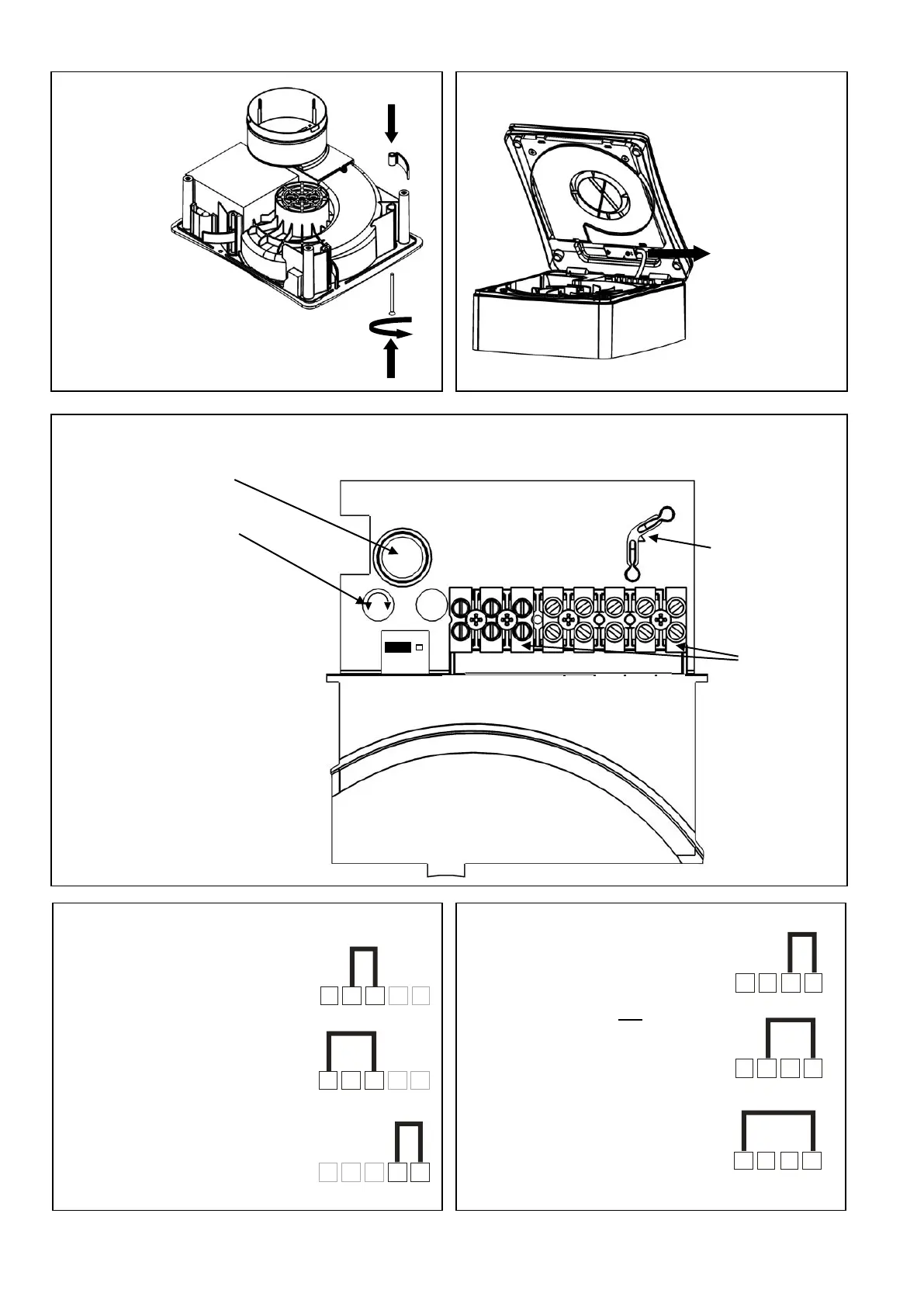
Fig. 7. Settings 427477B P & 427480B TM models only
Top view of PCB cover showing pot locations
jumper location and terminal location
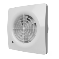
Recess mounting clips
In 3 positions
1 2 3 4L N LS
Low speed
1 2 3 4L N LS
Medium speed
1 2 3 4L N LS
High speed
do not have the ability to
switch from ‘constant
trickle’ to Normal or High
speed Boost. The fan can
switch from Off to either
Trickle, Normal or High
speed. For Constant
Trickle, Normal or High
speed (with no boost
option), switch the Pull-
cord (P model only) into
the On position and cut the
string.
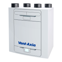
cover on TM
models the
sensor
lead must be
disconnected
must be used
with surface
(Not on P model)
(TM Models)
To reduce time
Turn Clockwise.
On P models
LS and 5 are
omitted.
On TM
models LS is
Omitted.
1 2 3 4 5
L N LS
1 2 3 4 5
L N LS
1 2 3 4 5
L N LS
Normal
speed boost
High speed
boost
To enable constant
trickle mode
Fig. 9. Settings – 427477B P model
Fig. 8. Settings – 427480B TM model
IMPORTANT: Do not link across terminals 1 and 2
Link terminals 2 and 3
for Normal boost speed.
Link terminals 1 and 3
for High boost speed.
Additional Link terminals
4 and 5 together for
constant trickle with boost
facility
 Loading...