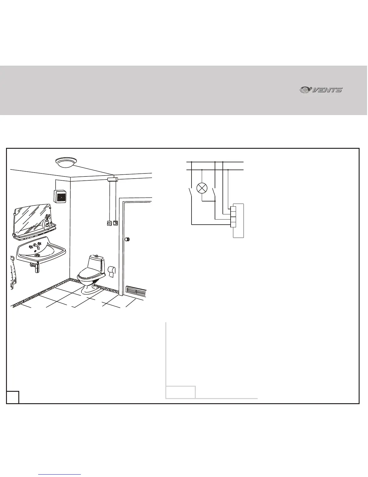
M
L
N
S1
LT
SB
L
N
A
EL
Sample schematic of basic two-speed fan model connection (modifications A, B and D) with a timer (T),
adjustable timer (TR) or interval switch (I).
68
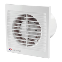
A - Fan
B - Distribution box
EL - Lighting lamp
S1 - lighting switch
(shown schematically).
SÂ - base load mode switch
(shown schematically).
EL
B
A
SÂ
S1
With a timer (Ò) or adjustable timer (TR):
If supplied with Ò and TR options the fan is constantly on operating at speed 1 with
SB switch closed or constantly off with the switch open.
You can set the fan to speed 2 manually using switch S1 which also doubles as the
light switch.
In this case the delay of switching to speed 2 is 50 seconds (option T) or
from 0 to 150 seconds (option TR).
On opening switch S1 the illumination on the premises is switched off whereas the
fan continues to operate according to the timer setting: for 6 minutes (T) or for
an interval from 2 to 30 minutes (TR) and then automatically switches to speed 1
or switches off.
With interval switch (I):
The fan equipped with an interval switch (I) constantly operates at speed 1 with
switch SB closed or remains off with the switch open.
Within the time interval manually set from 0.5 to 15 hours the fan automatically
switches to speed 2.
Speed 2 is engaged for 10 minutes.
Switch S1 used for swithing the fan to speed 2 also doubles as lighting switch.
The fan switches to speed 2 on elapsing of 50 second delay set on the timer.
On opening of switch S1 the lights on the premises switch off whereas the fan
reverts to the interval operation mode.
33
VNVN
Diagram 6
 Loading...