M
LT
N
L
N
EL
S1
L
SB
A
A
M
LT
N
L
N
EL
L
S1
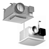
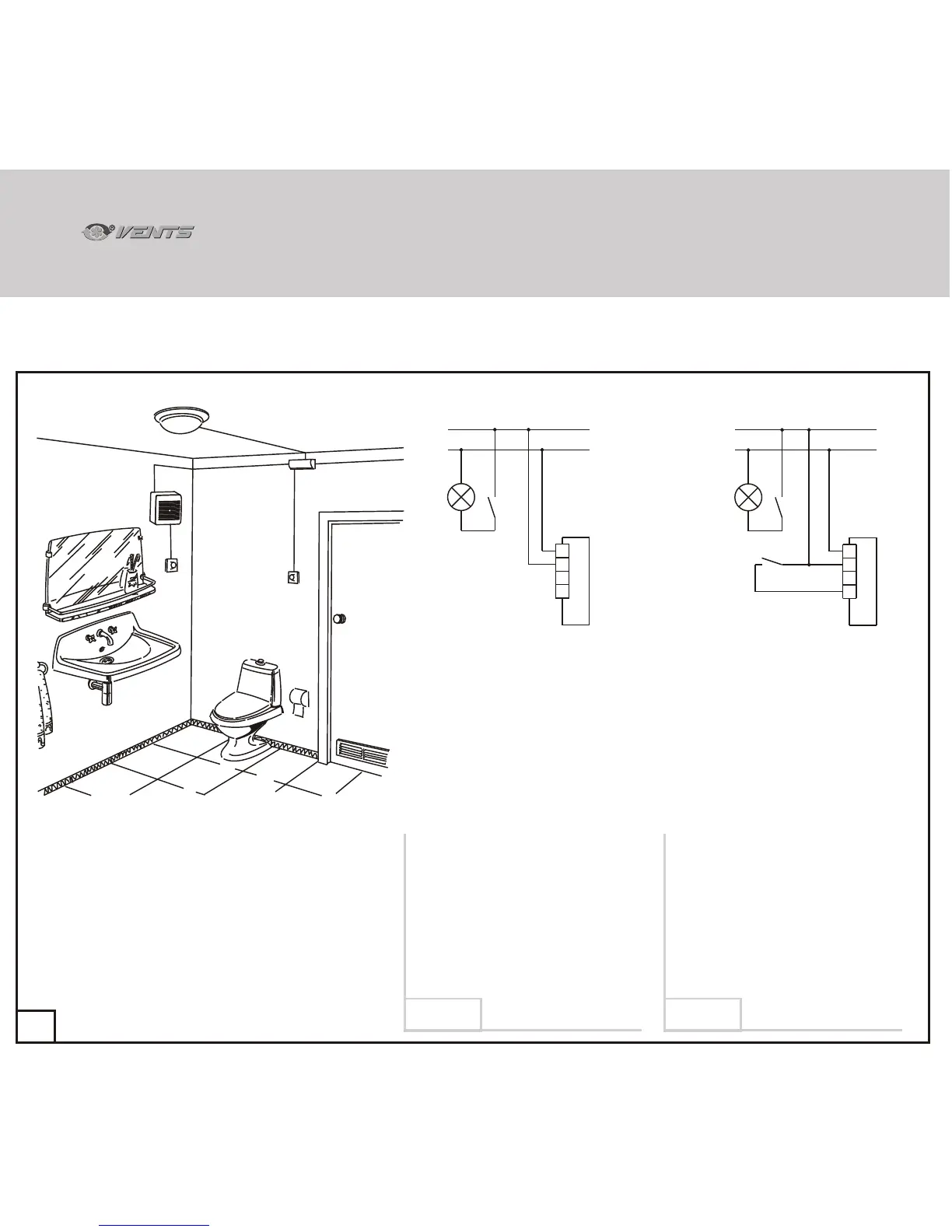
Sample schematic of basic two-speed fan model connection (modifications A, B and D) with photoelectronic sensors (F).
69
EL
B
A
S1
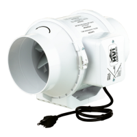
A - Fan
B - Distribution box
EL - Lighting lamp
S1 - lighting switch
(shown schematically)
SÂ - base load mode switch
(shown schematically).
SÂ
The fan initial state is off.
On switching the lights on the
photoelectric sensor sets the fan to
speed 2 on elapsing the 50 second
activation delay interval set on the timer.
On switching the lights off the fan
continues to operate until elapsing of the
timer setting which may range from
2 to 30 minutes and then switches off
automatically (speed 1 is not used in this
operation pattern).
The fan constantly operates at speed 1 with
switch SB closed or remains off with the
switch open.
On switching the lights on the photoelectric
sensor sets the fan to speed 2 on elapsing
of the 50 second activation delay set on
the timer.
On switching the lights off the fan
continues to operate until elapsing of the
timer setting which may range from
2 to 30 minutes and then automatically
switches to speed 1 or switches off.
34
VNVN
Diagram 8Diagram 7
 Loading...