or more than 5 seconds to power o
. Function Button USB One-Touch-Copy function is available when a USB storage
device is connected to the PowerBay NAS array
• Press momentarily to initiate
rom external USB
storage device to the PowerBay NAS array.
• Press and hold
or more than 3 seconds to sa
• When alarm buzzer is sounding, press button to cancel alarm.
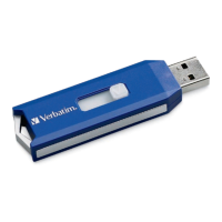
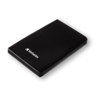
onnector • One USB 2.0 (Type A) connector: USB Host port for
connecting an external USB storage device
• Supports USB backup (copy
rom attached USB drive to
NAS array
• Provides additional stora
e as a shared volume on the LAN
• Supports USB Unlock Key for use with disk encryptio
counterclockwise to the Lock
osition to lock all
cartridges in place
. Power LED The power button contains a colored LED to indicate power
• Solid Red = Device is in Standb
tatus LED • Solid Green = Device o
erational status is Norma
• Blinking Green = Device is starting up or shutting dow
• Slide locking button to the le
Each HDD cartridge locking button contains a colored LED to
in
:
• Solid Blue = Disk Read
Blue = Data Access Activit
Error
• Solid Red = When all 4 cartridge LEDs are red indicates
Locked Encrypted Volum
ATA connector • One SATA-II (eSATA) connector for connecting external
storage device
fi les from attached eSATA
drive to NAS arra
• Provides additional storage as a shared volume on the LAN
(de
ault name “eSATA_1”)
• Supports mirror
unction between NAS array and attached
e
onnector USB Host Port. One USB 2.0 (Type A) connector; Power:
5V/500mA max. Used
• USB Printer; or
• USB UPS Monitor. If the attached UPS detects a power failure,
an automatic shutdown o
use
of this feature. Compatible with the following UPS equipment:
- AP
orts.
• Port 1 (LAN): For connecting the PowerBay NAS array to LAN.
This port supports Wake-On-LAN function.
• Port 2 (EXT): For real time backup to another PowerBay NAS
array
1
. Reset Button • Press and hold for more than 5 seconds to reset confi guration
to
13. Cooling Fans • Exhaust ports
acement
of the device is ver
lace the device in an enclosed
area suc
ore You Begin
Please read and make sure you understand all the prerequisites
our new device. Have all the necessar
information and equipment on hand before beginning the
in
ytes / 1 GB = 1,000,000,000
bytes / 1 TB = 1,000,000,000,000 bytes. Some capacity used
unctions, and thus is not available
or data storage. As a result,
and due to di
he default values for the PowerBay NAS array are as follows:
•