EasyManua.ls Logo

Verdant VX-TW - User Manual

Verdant VX-TW
24 pages
Print Icon
To Next Page IconTo Next Page
Loading...
VX-TW
Network
Installation
V.4 OCTOBER 20, 2015
.

Other manuals for Verdant VX-TW

Question and Answer IconNeed help?

Do you have a question about the Verdant VX-TW and is the answer not in the manual?

Summary

Whitelisting the Server

Installing the Online Connection Kit

Connecting the Antenna Module

Instructions for attaching the antenna to the wireless receiver and orienting it.

Connecting the Ethernet Cable

Steps to connect the server to the LAN port using an RJ-45 cable.

Powering on the Server

Guide on plugging the server into an electrical outlet and using a UPS.

Installing Thermostats

Pairing Thermostat and Wireless Control Card

Procedure for connecting the thermostat and control card using the programmer.

Installing the Wireless Control Card

Steps for wiring the control card to HVAC unit terminals, including wiring tables.

Mounting the Thermostat to the Wall

Instructions for removing cover, securing to wall, and installing batteries.

Configuring Thermostats

Setting the Thermostat Clock

Guide to setting the current time on the thermostat display for accurate operation.

Entering the Room Number

Instructions for inputting the room number for thermostat identification.

Configuring Compressor Type

Steps to set the compressor type (No Compressor, Heat Pump, Air Conditioner).

Configuring Electric Heat

Steps to set the electric heat option (No Electric Heat, Electric Heat).

Configuring Reversing Valve

Steps to set the reversing valve for cooling or heating mode.

Configuring Energy Saving Settings

Guide to selecting energy saving presets for thermostat operation.

Testing Thermostats

Testing HVAC Control

Procedures to test thermostat control of HVAC unit for heating, cooling, and fan speed.

Confirming Network Connectivity

Verifying Network Connection

Steps to log in to the management website and confirm thermostat presence.

Troubleshooting

Thermostat Control Issues

Diagnosing problems when the thermostat does not control the PTAC unit.

Low Battery Indicator

Action to take when the low battery indicator is displayed on the thermostat.

Error Codes

List of error codes and their meanings for thermostat malfunctions.

Warranty

Warranty Terms and Coverage

Details hardware/software warranty period, exclusions, and remedies.

Warranty Remedies and Service

Explains repair/replacement options and how to obtain warranty service.

Disclaimer of Liability

States limitations of liability for incidental or consequential damages.

Technical Specifications

Device Specifications

Technical details including dimensions, voltage, frequency, and accuracy.

Overview

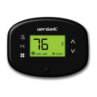
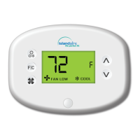
The Verdant VX-TW is a network-enabled thermostat system designed for use with PTAC (Packaged Terminal Air Conditioner) units, offering remote management and energy-saving capabilities. The system comprises a thermostat and a wireless control card, which communicate wirelessly with a central server.

Function Description:

The VX-TW system allows for precise control of heating, ventilation, and air conditioning (HVAC) units, specifically PTACs, in individual rooms. Its primary function is to provide temperature regulation, fan speed control, and energy-saving features. The thermostat can be configured locally or remotely via a management website, making it suitable for hospitality or commercial settings where centralized control is beneficial. The wireless control card acts as an interface between the thermostat and the HVAC unit, translating commands and monitoring the unit's status. The central server facilitates network connectivity, enabling remote monitoring, configuration, and data logging for all connected thermostats.

Important Technical Specifications:

  • Thermostat:

    • Case Dimensions (Imperial): 5.125" x 4.6875" x 1.25"
    • Case Dimensions (Metric): 130mm x 119mm x 32mm
    • Screen Dimensions (Imperial): 3.625" x 2.125"
    • Screen Dimensions (Metric): 92mm x 54mm
    • Operating Voltage: 3V DC - powered by two "C" Cell Batteries.
    • Occupancy Sensor Beam Width: ±47° (94°)
    • Wireless Frequency: 900MHz
    • Temperature Accuracy: ±1°F
    • FCC ID: XEYVX
    • IC: 8410A-VX
  • Wireless Control Card:

    • Case Dimensions (Imperial): 3.875" x 2.125" x 0.75"
    • Case Dimensions (Metric): 98mm x 54mm x 19mm
    • Operating Voltage: 24V AC/DC
    • Control Outputs: Fan High (GH), Fan Low (GL), Compressor (Y), Heat Pump (OB), Electric Heat (W2)
    • Wireless Frequency: 900MHz
  • Server (Online Connection Kit):

    • Requires a live Ethernet port with DHCP and the ability to connect outward via TCP to a remote machine.
    • MAC address is printed on the server for whitelisting.
    • Should be installed in a room adjacent to rooms with thermostats, not in the basement.
    • Wireless receiver and antenna must not be installed near metal structures or surfaces, as these significantly reduce wireless signal range.

Usage Features:

  • Installation Sequence: Installation begins with whitelisting the server's MAC address with the property system administrator. The Online Connection Kit (server, antenna module, and Ethernet cable) is then set up. Thermostat installation follows, starting with the room closest to the server and proceeding to adjacent rooms only after confirming network connectivity of previously installed thermostats. Rooms furthest from the server should be installed last.
  • Thermostat Pairing: The thermostat and wireless control card are paired using a Network Programmer. This involves connecting both devices to the programmer and pressing a button. It is crucial that neither the thermostat nor the control card is powered during this procedure (no batteries in the thermostat, no connection to the HVAC unit for the control card).
  • HVAC Unit Integration: The wireless control card connects to the thermostat terminals on the HVAC unit. The system supports both 24V AC and 24V DC HVAC units, with specific jumper settings on the control card for each. Proper wiring is guided by provided tables. The HVAC unit must be set to "External Thermostat" (Class 2) mode.
  • Thermostat Configuration: After power-up, the thermostat displays configuration settings. These include:
    • Setting the Clock: Crucial for proper operation. Hours and minutes are adjusted using "Up" and "Down" buttons, with "Fan" and "F/C" buttons for navigation.
    • Entering Room Number: Essential for networked thermostats, allowing for identification and remote management. Digits are changed with "Up" and "Down" buttons, and navigation with "Fan" and "F/C".
    • Equipment Settings:
      • Compressor Type: Configurable for "No Compressor" (0), "Heat Pump" (1), or "Air Conditioner" (2*).
      • Electric Heat: Configurable for "No Electric Heat" (0) or "Electric Heat" (1*).
      • Reversing Valve: Configurable to energize the PTAC OB valve to "COOL" (0) or "HEAT" (1*). Incorrect setting can lead to reversed heating/cooling operation.
    • Energy Saving Settings: Offers presets from "Energy Savings Off - No Temperature Setback" (0*) to "Highest Energy Savings" (5).
  • Remote Management: If connected to a network, equipment and energy-saving settings configured on the thermostat will be overridden by settings from the Remote Management Website. This centralized control is a key feature.
  • Network Connectivity Confirmation: After installation, it's vital to log into Verdant's Remote Management Website, navigate to the property, and confirm that the installed thermostat(s) appear with the correct room number. This step ensures successful network integration.

Maintenance Features:

  • Troubleshooting: The manual provides guidance for common issues:
    • Thermostat not controlling PTAC unit: Check if the HVAC unit is in "External Thermostat" mode.
    • Wireless Control Card red light status:
      • Off: Indicates no power to the control card; verify wiring.
      • Blinking with one (1) flash: Control card is powered but not connected to the thermostat; re-link using the Network Programmer.
      • Blinking with three (3) flashes or continuously flashing: Control card is connected to the thermostat; check control card wiring and thermostat configuration.
    • Low Battery Indicator: Replace thermostat batteries.
  • Error Codes: The thermostat displays specific error codes to aid in diagnosis:
    • ERR 1: Thermostat Temperature Sensor Hardware Defect.
    • ERR 2: Thermostat Radio Hardware Defect.
    • ERR 3: Thermostat Radio Software Defect.
    • ERR 4: No link with the Wireless Control Card.
    • ERR 5: Thermostat Memory Defect.
  • Warranty: Verdant provides a one-year warranty for hardware (defects in workmanship and materials) and software (conformance to program specifications). Exclusions include physical damage, misuse, improper installation, unauthorized repairs, environmental damage (accident, fire, water, humidity), or issues caused by incompatible devices. Remedies for covered defects are repair or replacement at Verdant's option. Warranty service is obtained by following Verdant's "Warranty Replacement Procedure."

Verdant VX-TW Specifications

General IconGeneral
BrandVerdant
ModelVX-TW
CategoryThermostat
LanguageEnglish

Related product manuals