Troubleshooting Guide
Symptom: Potential Cause(s): Recommendation(s):
Pump Cycles Once
Deadhead (system pressure meets or exceeds air
supply pressure).
Increase the inlet air pressure to the pump. Pump is designed for 1:1 pressure ratio at zero ow.
(Does not apply to high pressure 2:1 units).
Air valve or intermediate gaskets installed incorrectly. Install gaskets with holes properly aligned.
Bent or missing actuator plunger. Remove pilot valve and inspect actuator plungers.
Pump Will Not Operate
/ Cycle
Pump is over lubricated. Set lubricator on lowest possible setting or remove. Units are designed for lube free operation.
Lack of air (line size, PSI, CFM). Check the air line size and length, compressor capacity (HP vs. cfm required).
Check air distribution system. Disassemble and inspect main air distribution valve, pilot valve and pilot valve actuators.
Discharge line is blocked or clogged manifolds. Check for inadvertently closed discharge line valves. Clean discharge manifolds/piping.
Deadhead (system pressure meets or exceeds air
supply pressure).
Increase the inlet air pressure to the pump. Pump is designed for 1:1 pressure ratio at zero ow.
(Does not apply to high pressure 2:1 units).
Blocked air exhaust mufer. Remove mufer screen, clean or de-ice, and re-install.
Pumped uid in air exhaust mufer. Disassemble pump chambers. Inspect for diaphragm rupture or loose diaphragm plate assembly.
Pump chamber is blocked. Disassemble and inspect wetted chambers. Remove or ush any obstructions.
Pump Cycles and Will
Not Prime or No Flow
Cavitation on suction side. Check suction condition (move pump closer to product).
Check valve obstructed. Valve ball(s) not seating
properly or sticking.
Disassemble the wet end of the pump and manually dislodge obstruction in the check valve pocket.
Clean out around valve ball cage and valve seat area. Replace valve ball or valve seat if damaged.
Use heavier valve ball material.
Valve ball(s) missing (pushed into chamber or
manifold).
Worn valve ball or valve seat. Worn ngers in valve ball cage (replace part). Check Chemical
Resistance Guide for compatibility.
Valve ball(s)/seat(s) damaged or attacked by product. Check Chemical Resistance Guide for compatibility.
Check valve and/or seat is worn or needs adjusting. Inspect check valves and seats for wear and proper setting. Replace if necessary.
Suction line is blocked. Remove or ush obstruction. Check and clear all suction screens or strainers.
Excessive suction lift. For lifts exceeding 20’ of liquid, lling the chambers with liquid will prime the pump in most cases.
Suction side air leakage or air in product. Visually inspect all suction-side gaskets and pipe connections.
Pumped uid in air exhaust mufer. Disassemble pump chambers. Inspect for diaphragm rupture or loose diaphragm plate assembly.
Pump Cycles Running
Sluggish/Stalling,
Flow Unsatisfactory
Over lubrication. Set lubricator on lowest possible setting or remove. Units are designed for lube free operation.
Icing. Remove mufer screen, de-ice, and re-install. Install a point of use air drier.
Clogged manifolds. Clean manifolds to allow proper air ow
Deadhead (system pressure meets or exceeds air
supply pressure).
Increase the inlet air pressure to the pump. Pump is designed for 1:1 pressure ratio at zero ow.
(Does not apply to high pressure 2:1 units).
Cavitation on suction side. Check suction (move pump closer to product).
Lack of air (line size, PSI, CFM). Check the air line size, length, compressor capacity.
Excessive suction lift. For lifts exceeding 20’ of liquid, lling the chambers with liquid will prime the pump in most cases.
Air supply pressure or volume exceeds system hd. Decrease inlet air (press. and vol.) to the pump. Pump is cavitating the uid by fast cycling.
Undersized suction line. Meet or exceed pump connections.
Restrictive or undersized air line. Install a larger air line and connection.
Suction side air leakage or air in product. Visually inspect all suction-side gaskets and pipe connections.
Suction line is blocked. Remove or ush obstruction. Check and clear all suction screens or strainers.
Pumped uid in air exhaust mufer. Disassemble pump chambers. Inspect for diaphragm rupture or loose diaphragm plate assembly.
Check valve obstructed. Disassemble the wet end of the pump and manually dislodge obstruction in the check valve pocket.
Check valve and/or seat is worn or needs adjusting. Inspect check valves and seats for wear and proper setting. Replace if necessary.
Entrained air or vapor lock in chamber(s). Purge chambers through tapped chamber vent plugs. Purging the chambers of air can be dangerous.
Product Leaking
Through Exhaust
Diaphragm failure, or diaphragm plates loose. Replace diaphragms, check for damage and ensure diaphragm plates are tight.
Diaphragm stretched around center hole or bolt holes. Check for excessive inlet pressure or air pressure. Consult Chemical Resistance Chart for compatibility
with products, cleaners, temperature limitations and lubrication.
Premature Diaphragm
Failure
Cavitation. Enlarge pipe diameter on suction side of pump.
Excessive ooded suction pressure. Move pump closer to product. Raise pump/place pump on top of tank to reduce inlet pressure.
Install Back pressure device (Tech bulletin 41r). Add accumulation tank or pulsation dampener.
Misapplication (chemical/physical incompatibility). Consult Chemical Resistance Chart for compatibility with products, cleaners, temperature limitations
and lubrication.
Incorrect diaphragm plates or plates on backwards,
installed incorrectly or worn.
Check Operating Manual to check for correct part and installation. Ensure outer plates have not been
worn to a sharp edge.
Unbalanced Cycling
Excessive suction lift. For lifts exceeding 20’ of liquid, lling the chambers with liquid will prime the pump in most cases.
Undersized suction line. Meet or exceed pump connections.
Pumped uid in air exhaust mufer. Disassemble pump chambers. Inspect for diaphragm rupture or loose diaphragm plate assembly.
Suction side air leakage or air in product. Visually inspect all suction-side gaskets and pipe connections.
Check valve obstructed. Disassemble the wet end of the pump and manually dislodge obstruction in the check valve pocket.
Check valve and/or seat is worn or needs adjusting. Inspect check valves and seats for wear and proper setting. Replace if necessary.
Entrained air or vapor lock in chamber(s). Purge chambers through tapped chamber vent plugs.
For additional troubleshooting tips contact After Sales Support at service.warrenrupp@idexcorp.com or 419-524-8388
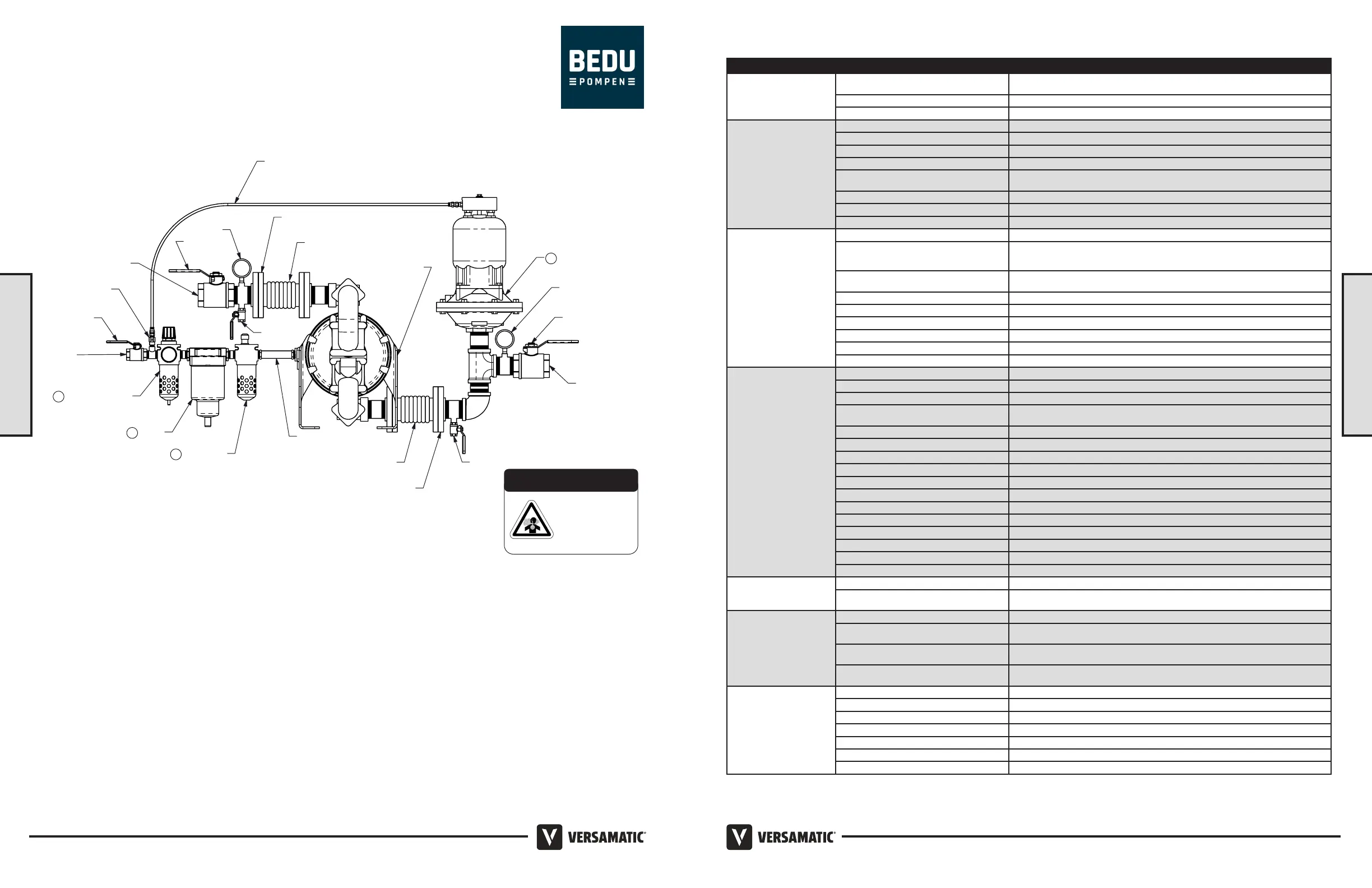
Recommended Installation Guide
1
Surge Suppressor
Flexible Connector
Pipe Connection
(Style Optional)
Shut-Off Valve
Pressure Gauge
Drain Port
Muffler
(Optional Piped Exhaust)
Flexible
Connection
3
Dryer
Unregulated Air
Supply to Surge
Suppressor
Shut Off
Valve
Flexible Connector
Pipe Connection
(Style Optional
Drain Port
Shut-Off
Valve
Compound
Gauge
Suction Port
Discharge Port
Air Inlet
2
Filter Regulator
4
Lubricator
Check Valve
Note
: Surge Suppressor and
Piping, including air line,
must be supported after
the flexible connections.
Installation And Start-Up
Locate the pump as close to the product being pumped as possible. Keep the suction line length and number of ttings to a minimum. Do not reduce the suction line
diameter.
Air Supply
Connect the pump air inlet to an air supply with sufcient capacity and pressure to achieve desired performance. A pressure regulating valve should be installed to
insure air supply pressure does not exceed recommended limits.
Air Valve Lubrication
The air distribution system is designed to operate WITHOUT lubrication. This is the standard mode of operation. If lubrication is desired, install an air line lubricator
set to deliver one drop of SAE 10 non-detergent oil for every 20 SCFM (9.4 liters/sec.) of air the pump consumes. Consult the Performance Curve to determine air
consumption.
Air Line Moisture
Water in the compressed air supply may cause icing or freezing of the exhaust air, causing the pump to cycle erratically or stop operating. Water in the air supply can
be reduced by using a point-of-use air dryer.
Air Inlet And Priming
To start the pump, slightly open the air shut-off valve. After the pump primes, the air valve can be opened to increase air ow as desired. If opening the valve
increases cycling rate, but does not increase the rate of ow, cavitation has occurred. The valve should be closed slightly to obtain the most efcient air ow to pump
ow ratio.
Available Accessories:
1. Surge Suppressor
2. Filter/Regulator
3. Air Dryer
4. Lubricator
CAUTION
The air exhaust should
be piped to an area
for safe disposition
of the product being
pumped, in the event of
a diaphragm failure.
UNIVERSAL ALL AODD UNIVERSAL ALL AODD, EXCEPT FLAP
Model E2 Bolted Plastic Flap • 98
• Model E2 Bolted Plastic Flap
2: INSTAL & OP
2: INSTAL & OP
 Loading...