Do you have a question about the VERSARE Room Divider and is the answer not in the manual?
Lists the necessary tools for assembly, including 7/16", 1/2", and 9/16" wrenches.
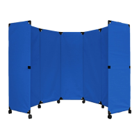
Position the partition assembly flat on the floor as illustrated.
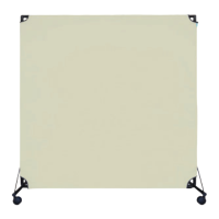
Identify and locate the left top panel of the partition.
Position one of the end panels on top of the main assembly.
Insert a 9/16" bolt into the top hole on both ends, tightening by hand initially.
Rotate the first panel 90 degrees as shown in the diagram.
Insert a 7/16" bolt into the top and bottom holes.
Find the rectangular nut, slide it up the channel, and align it with the open hole.
Insert a ½” bolt into the rectangular nut at the top and bottom of the partition.
Securely tighten all previously inserted bolts.
Rotate the partition assembly so it rests against the back of the end panel.
Position the second end panel onto the partition assembly as depicted.
Insert a 9/16" bolt into the top hole on both ends.
Insert a 7/16" bolt into the top and bottom holes.
Insert a ½” bolt into the rectangular nut at the top and bottom.
Perform a final tightening of all bolts to secure the structure.
Secure the transport lock as shown in the illustration.
Carefully lift the assembled partition into its upright position.
| Type | Room Divider |
|---|---|
| Features | Portable |
| Height | 72 inches |
| Foldable | Yes |
| Wheeled | Yes |
| Material | Fabric, Metal |