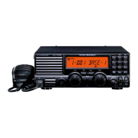
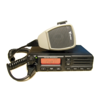
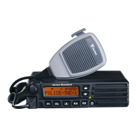
VX-1210
Alignment
3
Tune to: Adjust or Confirm: For:
“VCO1 U” channel (8.9999 MHz, USB)
T2001
6.0 V ±0.1 V
“VCO1 L” channel (0.50000 MHz, USB)
Confirm 1.3 ~ 2.3 V
“VCO2 U” channel (18.9999 MHz, USB)
T2002
6.0 V ±0.1 V
“VCO2 L” channel (9.00000 MHz, USB)
Confirm 1.0 ~ 2.0 V
“VCO3 U” channel (30.00000 MHz, USB)
T2003
6.0 V ±0.1 V
“VCO3 L” channel (19.00000 MHz, USB)
Confirm 1.0 ~ 2.0 V
1st Local Output Level
r Connect the RF millivoltmeter to TP1001 on MAIN Unit.
r Confirm that the output level is 13 dBm ±3 dB.
Receiver Alignment
RX IF Coils Alignment
r Connect the RF Signal Generator to ANT jack, and connect the DC voltmeter to TP1005 on the
MAIN Unit.
r Select the “RX IF” channel (10.15000 MHz, USB).
r Inject a signal from the RF Signal Generator to 10.15100 MHz, then adjust the RF Signal
Generator output level so that the DC voltmeter reading is approximately 3 V.
r Adjust T1008, T1009, T1010, T1011, T1012, T1015, T1016, and T1017 in succession several
times for minimum indication on the DC Voltmeter.
RX Gain Alignment
r Connect the RF Signal Generator to ANT jack, and connect the DC voltmeter to TP1005 on the
MAIN Unit.
r Select the “RX IF” channel (10.15000 MHz, USB), and recall the [RX GAIN] parameter on the
computer.
r Inject a signal from the RF Signal Generator to 10.15100 MHz, then adjust the RF Signal
Generator output level for 6 dBµ.
r Press the UP(π)/DOWN(θ) key so that the difference of the DC Voltmeter reading is 0.2 V ±0.1
V when the RF Signal Generator on and off.
Noise Blanker Alignment
r Connect the RF Signal Generator to ANT jack, and connect the DC voltmeter to TP1004 on the
MAIN Unit.
r Select the “RX IF” channel (10.15000 MHz, USB).
r Inject a signal from the RF Signal Generator to 10.15100 MHz, then adjust the RF Signal
Generator output level so that the DC voltmeter reading is approximately 3 V.
r Adjust T1013 and T1014 for minimum indication on the DC Voltmeter.
47.055 MHz IF Trap Alignment
r Connect the RF Signal Generator to ANT jack, and connect the DC voltmeter to TP1005 on the
MAIN Unit.
r Select the “IF TRAP” channel (30.00000 MHz, USB).
r Inject a signal from the RF Signal Generator to 47.05400 MHz, then adjust the RF Signal
Generator output level for 100 dBµ.
r Adjust T1002 for maximum indication on the DC Voltmeter.
 Loading...
