Page 2 VX-1700 OPERATING MANUAL
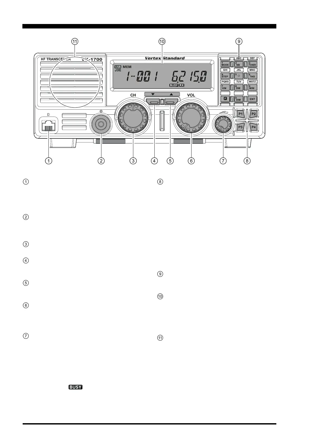
MIC Jack
This modular jack accepts microphone voice input,
as well as scanning and PTT (Push To Talk) control
from the microphone. Specified microphone imped-
ance is 500 - 600 Ohms.
POWER Switch
This is the main on/off switch for the VX-1700. Press
and hold in this switch for one second to toggle the
transceiver’s power on and off.
CH
(
Channel
)
Selector Knob
The Channel selector knob selects memory channels.
(
Down
)
Button
Pressing this button move the memory group to the
next-lowest group.
(
UP
)
Button
Pressing this button move the memory group to the
next-highst group.
VOL Knob
This control adjusts the receiver audio volume from
the speaker. Clockwise rotation of this control in-
creases the volume level.
SQL Knob
This control may be used silence the receiver when
no signals are being received. Clockwise rotation of
this control causes the receiver to respond only to pro-
gressively stronger signals; conversely, counter-clock-
wise rotation of this control allows progressively
weaker signals to be heard.
When a signal or noise breaks through the squelch
“threshold,” the “ ” icon on the display will be
illuminated.
FRONT PANEL CONTROLS & SWITCHES
P1 - P4 Keys
(
PROGRAMMABLE FUNCTION KEYS
)
These four keys functions can be customized, via pro-
gramming by your Vertex Standard dealer. The fac-
tory defaults are shown below.
P1 Key: Press this key to tune the receiver frequency
downward without changing the transmit
frequency (Clarifier function).
P2 Key: Toggles the Key Lockout feature “on” and
“off.”
P3 Key: Press this key to tune the receiver frequency
upward without changing the transmit fre-
quency (Clarifier function).
P4 Key: Turns the internal speaker (or external
speaker, if used) “on” and “off.”
Keypad
These twelve keys are used for certain operational
commands (described in subsequent chapters).
LCD Display
This multi function LCD (Liquid Crystal Display) in-
cludes frequency readout or Alpha/Numeric “Tag”
labeling of the channel in use, plus a Signal Strength/
Power Output meter, and icons which provide visual
confirmation of transceiver status.
Speaker
The internal speaker is located here.

 Loading...