VXR-7000 FM REPEATER OPERATING MANUAL2
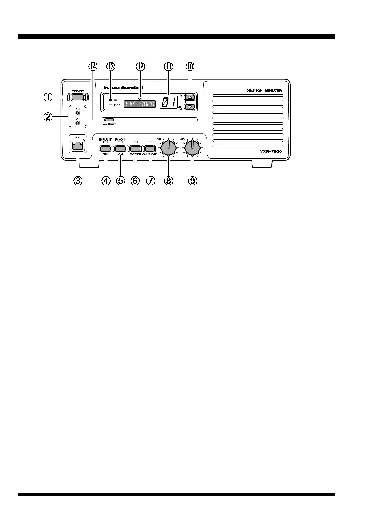
Controls & Connectors
①
POWER Switch
This is the main power switch for the repeater.
②
LED Indicators
AC: This LED glows green during AC operation.
DC: This LED glows yellow during DC operation.
③
MIC Jack
This 8-pin modular jack accepts the microphone in-
put, and provides a standby control line to activate
the transmitter when using the “BASE” mode of
operation. This jack also provides a “Hook” control
line, as well as a “Clone Data” line.
④
BASE/REPEATER Switch
This switch toggles the operating mode between the
“REPEATER” mode and the “BASE” transceiver
mode. When the “REPEATER” mode is selected, the
LED above it glows green. While in the “BASE”
mode (the green LED is off), you can speak into the
microphone to use it as a transceiver. For normal
repeater operation, set this switch to the “RE-
PEATER” mode.
⑤
LOCAL/REMOTE Switch
This switch toggles the control mode between the
“REMOTE” mode and “LOCAL” mode. When the
“LOCAL” mode is selected, the LED above it is off,
and the repeater operates according to the control
data programmed into the repeater. While in the
“REMOTE” mode, the LED glows green, and the
repeater operates according to the control instruc-
tions received from an external device (connected
to the ACC jack on the rear panel).
⑥
MONITOR Switch
This switch selects the “Squelch” (receiver mute)
mode. When the green LED above it is off, “Tone”
or “Coded” squelch is active. When you press this
switch momentarily, the green LED will glow steadily;
in this condition, only “noise squelch” is active, and
any signal present on the channel will be heard. If
you press and hold this switch for more than 2 sec-
ond, the green LED will blink and the squelch will
open; in this condition, background noise will be
heard if no signal is present.
⑦
ACCESSORY Switch
This switch can be set up for special applications,
such as High/Low power selection, as determined
by your Vertex Standard dealer. The LED above it
glows green when this function is activated. For fur-
ther details, contact your Vertex Standard dealer.
⑧
VOL Knob
This control knob adjusts the receiver volume level
from the front panel speaker. If desired, this control
knob may be set fully counterclockwise when re-
peater monitoring is not needed.
⑨
SQL Knob
This control knob selects the noise squelch thresh-
old level. Set it to a position just above the point
where the BUSY lamp goes out when no signal is
present.
⑩
Channel Selector Buttons (p and q)
Press one of these buttons to select the operating
channel.
Front Panel
 Loading...