VXR-7000 FM REPEATER OPERATING MANUAL 5
Pin 13: GND
Chassis ground for all logic levels and power sup-
ply return.
Pin 14: GND
Chassis ground for all logic levels and power sup-
ply return.
Pin 15: N.C. (No connection.)
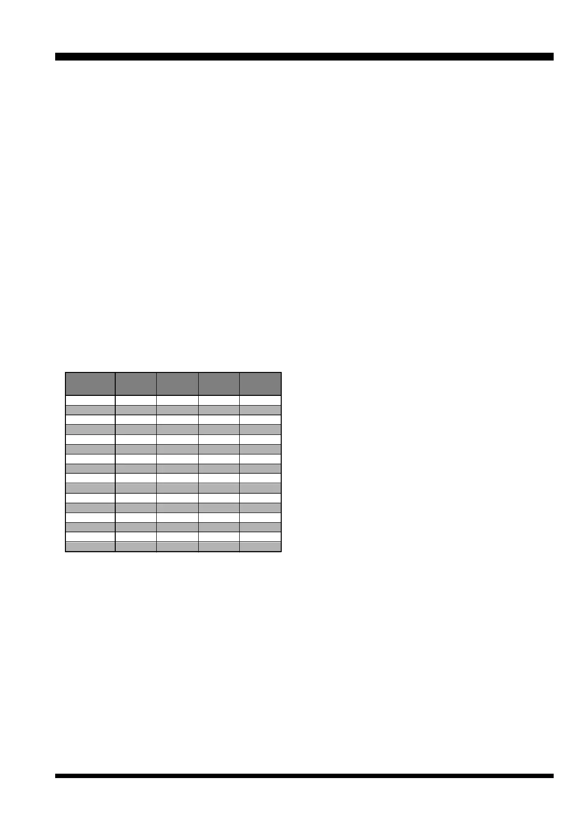
Pin 16, 17, 18, & 19: REMOTE CH DATA
[Logic Inputs D3, D2, D1, and D0] (Active Low)
These inputs are internally pulled up to 5-V DC.
When pulled low by an external device, they select
one of the 16 pre-programmed repeater operating
channels. The logic truth table below shows the com-
binations for selecting all 16 channels.
In the truth table, “1” represents no connection, and
“0” represents a ground connection on the pin.
The channel selection logic is not inhibited while the
transmitter is keyed: the repeater will change fre-
quency when instructed, even while transmitting.
Avoid voltage in excess of 5 V on these pins or inter-
nal damage to the microprocessor on the repeater
CNTL Unit may result.
ACC Connector Port
Pin 20: GND
Chassis ground for all logic levels and power sup-
ply return.
Pin 21: A-OUTPUT [Logic Output] (Active Low)
This open collector logic output is pulled low when
the front panel’s ACCESSORY key is turned on. It
can sink approx. 10 mA when active.
Pin 22: RXD LOW
[Digital Output for DATA Communications]
(300 ~ 3,000 Hz)
This pin is an output for low speed receiving data
signals, with the data being extracted after the de-
emphasis and low pass filter stages.
Pin 23: RXD HI
[Digital Output for DATA Communications]
This pin is an output for high speed receiving data
signals, with the data being extracted immediately
after the discriminator prior to any de-emphasis).
Pin 24: TXD LOW
[Digital Input for DATA Communications]
(300 ~ 3,000 Hz)
This pin is intended to be used as a low speed digi-
tal data signal input to the repeater. This digital data
signal is injected before transmitter pre-emphasis
and limiting stage, so excess signal input levels are
clipped.
Pin 25: TXD HI
[Digital Input for the DATA Communications]
This pin is intended to be used as a high speed digi-
tal data signal input to the repeater. This digital data
signal is injected after transmitter splatter filter stage.
Channel
1
2
3
4
5
6
7
8
9
10
11
12
13
14
15
16
Pin 17
(
D2
)
1
1
1
1
0
0
0
0
1
1
1
1
0
0
0
0
Pin 18
(
D1
)
1
1
0
0
1
1
0
0
1
1
0
0
1
1
0
0
Pin 19
(
D0
)
1
0
1
0
1
0
1
0
1
0
1
0
1
0
1
0
Pin 16
(
D3
)
1
1
1
1
1
1
1
1
0
0
0
0
0
0
0
0
 Loading...