14 VXR-7000 UHF Service Manual
Operating Manual Reprint
Duplexer Installation
Important Notes!
Please refer to the operating manual for your
Duplexer for details regarding maximum power
input, TX/RX connector locations, etc) before in-
stalling the Antenna Duplexer.
Be certain to observe and comply with the speci-
fications for frequency separation and maximum
transmitter power for the duplexer connected to
the VXR-7000, particularly when using the VXD-
40xx internal duplexer. When the VXD-40xx is
used, the frequency separation must be 5 MHz
(minimum) to 10 MHz (maximum), and the
maximum transmitter power output allowed is
40 Watts.
If the VXR-7000 output power (50 Watts) is in
excess of the range of the duplexer's capability,
you may reduce the TX output power of the
VXR-7000 before installing the Antenna Du-
plexer, using the following procedure:
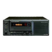
1. Connect the VXR-7000’s TX antenna port to a watt-
meter and dummy load (the duplexer must not be con-
nected at this point). Connect any Vertex Standard
microphone to the MIC jack, and place the BASE/
REPEATER switch in the “BASE” position. Select
Channel 1 for alignment purposes.
2. Press and hold in the ACCESSORY switch for two
seconds to enter the adjustment mode. The channel
number will begin to blink.
3. Press and hold in the PTT key on the microphone.
The display will indicate “Po” while transmitting. Ob-
serve the power output as indicated on the watmeter.
4. Press the (UP: increment) or (DOWN: decre-
ment) button (to the right of the channel display) re-
peatedly to adjust the TX output power to 40 Watts
(or less) while holding in the PTT key.
5. Once the desired power level has been obtained, re-
lease the PTT key. Now press and hold in the AC-
CESSORY button for at least two seconds to save
the new setting and exit to the normal operation.
6. Repeat steps 2. through 5. (above) for any other chan-
nels (2 through 16) if they are to be used.
7. Re-test each channel in the normal operating mode to
confirm the proper power output. You may now dis-
connect all test equipment.
8. The duplexer may now be installed.
The above procedure should only be performed by your
Authorized Vertex Standard Dealer or a qualified radio
technician, in order to ensure accurate calibration. Please
consult with your Authorized Vertex Standard Dealer for
assistance with procurement of a suitable duplexer.

 Loading...