Do you have a question about the Vertiv EDGE-750IMT and is the answer not in the manual?
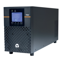
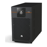
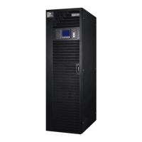
Visual representations of various VERTIV EDGE UPS models.
Lists and describes the ports and components of the UPS units.
Important notes on safety statements and detailed user guides.
Check the UPS for any signs of obvious damage before proceeding.
Select a suitable environment, ensuring proper ventilation and clearance.
Instructions for installing the UPS in tower or rack configurations.
Guidance on connecting critical and less-critical equipment to the UPS.
Connect via USB for unattended shutdown software integration.
Connect the EPO connector for immediate emergency shutdown.
Connect optional battery cabinets for extended runtime.
Connect the UPS to a properly protected AC power source.
Procedure to power on the UPS and initiate battery self-test.
Steps for normal and fully shutting down the UPS unit.
Safety precautions before performing battery maintenance.
Steps to safely remove the existing battery from the UPS.
Instructions for installing the new battery and reassembling the UPS.
Navigate UPS settings to confirm battery replacement.
Guidance on proper disposal or return of old batteries.
The Vertiv EDGE UPS 500-3000VA I is an uninterruptible power supply designed to provide reliable power protection for critical equipment. This device ensures continuous operation and safeguards connected devices from power fluctuations, outages, and other electrical disturbances. It is suitable for a wide range of applications, from small office environments to more demanding infrastructure needs.
The primary function of the Vertiv EDGE UPS is to provide backup power during utility power failures, allowing connected equipment to continue operating or to be shut down gracefully. It achieves this by converting stored battery power into AC power for the connected loads. The UPS also offers surge protection, filtering incoming AC power to protect sensitive electronics from spikes and noise.
The device features both non-programmable and programmable rear outlets. Critical equipment, such as computers and monitors, should be connected to the non-programmable outlets to ensure constant power. Less critical equipment, like printers or other peripherals, can be connected to the programmable outlets, which can be controlled to extend battery runtime for essential devices during an outage.
For enhanced communication and control, the UPS includes a USB communication port. This allows the UPS to connect to a computer, enabling unattended, controlled shutdowns of the computer in the event of a UPS input power failure. The UPS is compatible with built-in software within Microsoft® Windows® operating systems or with Vertiv Power Assist Shutdown software, available from Vertiv.
An optional Emergency Power Off (EPO) connector is also available. This feature allows for the internal disconnection of all power sources to the UPS and connected equipment during an emergency, complying with national and local wiring codes and regulations. Users can remove a factory-installed jumper on the rear panel EPO connector and connect to active-open contacts that are normally closed but open during an emergency power-off event. The operating logic for this feature can be reversed in the Settings menu. If the EPO connector is not used, the factory-installed jumper should remain in place.
The Vertiv EDGE UPS also supports external battery cabinets (EBCs) to provide extended battery run-time for connected devices. Up to six external battery cabinets can be connected to the UPS, significantly increasing the duration of backup power available.
The Vertiv EDGE UPS is designed for flexible installation, supporting both tower and rack configurations. For tower installation, users assemble and attach the provided tower support stands. For rack installation, brackets are attached to the UPS, and a rail kit can be installed in the rack if needed, before the UPS is mounted.
Choosing an appropriate location for the UPS is crucial for optimal performance and longevity. It should be installed in a temperature-controlled environment, free from corrosive and conductive contaminants. Locations near heat or water sources, or those exposed to direct sunlight, should be avoided. To ensure proper ventilation, a minimum of four inches of clearance should be maintained on all sides of the UPS. The input outlet for the UPS should be nearby and easily accessible.
Starting up the UPS involves plugging it into a stable 230VAC source. The LCD display will turn on, and the batteries will begin charging. To turn on the output, the ENTER/ button must be pressed and held for two seconds. The UPS will then enter a 10-second Battery Self Test mode before transitioning to On Mode.
Shutting down the UPS involves pressing and holding the ENTER/ button for two seconds and confirming the shutdown via a pop-up window on the display. This action will turn off the outlets. For a complete shutdown, the input power should also be disconnected.
For external status monitoring, the UPS features a network communications port where optional network cards can be installed. Compatible cards include the IntelliSlot Relay card (IS-UNITY-SNMP) and the IntelliSlot RDU101 card (RDU101). Installation involves removing two screws and a protective cover, inserting the card, and securing it with the screws.
Connecting AC input is straightforward: ensure all loads are powered off, then connect the UPS to an input-power supply/wall outlet that is properly protected by a circuit breaker and grounded, in accordance with national and local electrical codes. Once plugged in, the UPS will begin charging its battery.
Regular maintenance ensures the longevity and optimal performance of the Vertiv EDGE UPS. The batteries are valve-regulated, non-spillable, lead-acid, and should be kept charged to attain their design life. The UPS continuously charges the batteries when connected to utility input power. If the UPS is to be stored for an extended period, it is recommended to connect it to input power for at least 24 hours every four to six months to ensure a full recharge of the batteries.
Replacing the battery pack is a key maintenance task. Users can safely replace the internal battery pack. Before proceeding, it is important to review the battery safety precautions available on the Vertiv website. The replacement battery should be of the same type and number as originally installed. The User Guide provides the part number for the replacement battery specific to each UPS model.
The battery replacement process involves several steps:
For cleaning, the UPS should be turned off and unplugged. It should be cleaned with a dry cloth; liquid or aerosol cleaners should not be used. It is also important to never block or insert any objects into the UPS ventilation holes or openings, and to ensure the power cord is not placed where it might be damaged.
For detailed installation, operating, maintenance, and troubleshooting information, users should refer to the EDGE User Guide available on the Vertiv website.
| Model | EDGE-750IMT |
|---|---|
| Type | Line-Interactive |
| Form Factor | Tower |
| Communication Ports | USB |
| Topology | Line-Interactive |
| Input Frequency | 50/60 Hz |
| Capacity | 750 VA |
| Output Power | 500W |
| Input Voltage | 120V |
| Output Voltage | 120V |
| Battery Type | Sealed Lead Acid |
| Waveform | Sine Wave |
| Transfer Time | Typical 4-6 ms |
| Battery Recharge Time | 4-6 hours |
| Efficiency | Up to 98.0% |