REV : 5
REV DATE : 1/20
DPN004208
Page :1 /1
Form No.: DPN001040_REV4
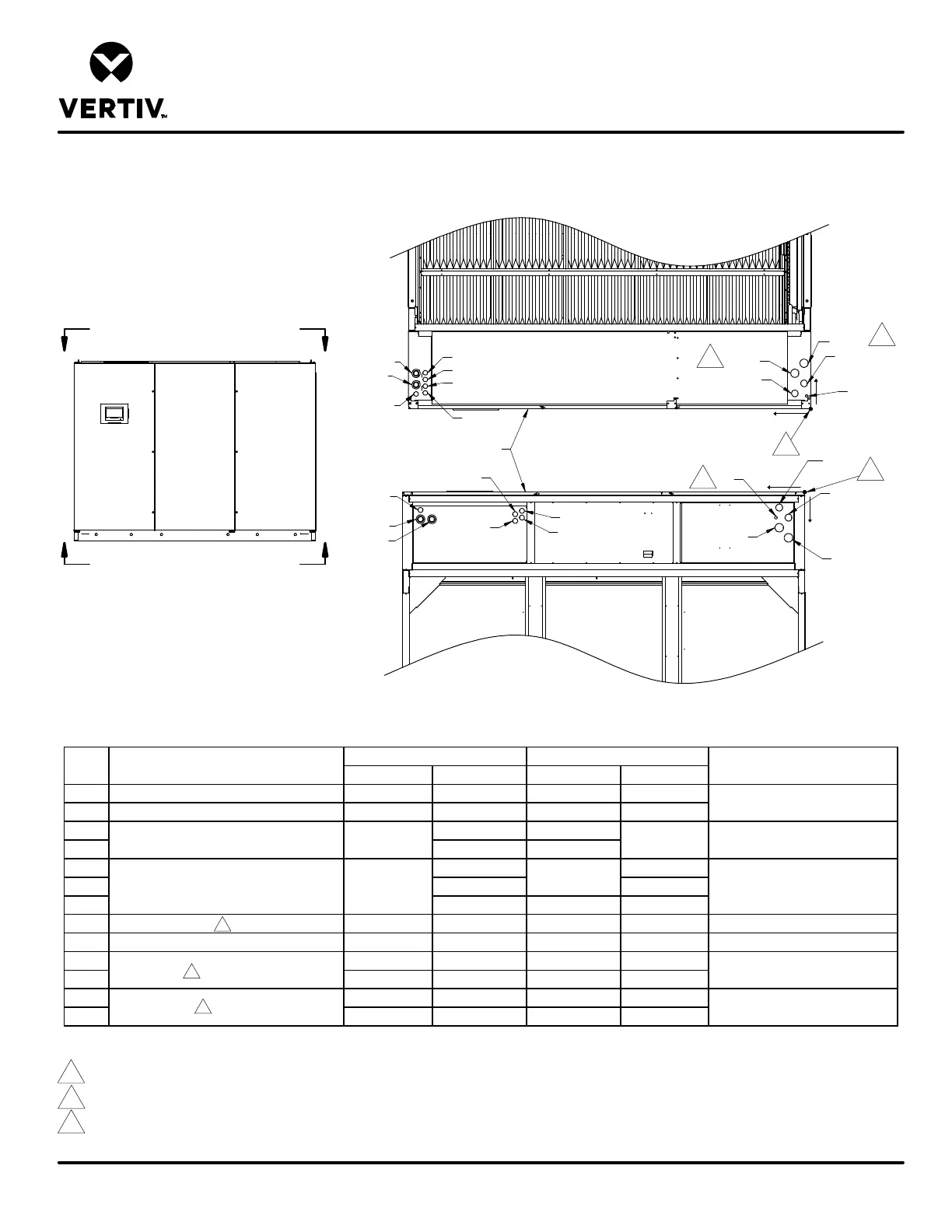
PRIMARY CONNECTION LOCATIONS
LIEBERT
®
DSE
DA250, DA265
X in. (mm) Y in. (mm) X in. (mm) Y in. (mm)
HR HV Heat Rejection High Voltage 117-1/2 (2984) 4-1/2 (113) 114-3/8 (2904) 5-3/8 (136)
HR LV Heat Rejection Low Voltage 114-3/4 (2914) 4-3/4 (122) 86-1/8 (2189) 6-5/8 (168)
HV1 10-5/8 (269) 114-3/8 (2904)
HV2 7-1/4 (183) 111 (2818)
LV1 10-3/4 (274) 5-5/8 (142)
LV2 8-3/4 (223) 7-5/8 (193)
LV3 6-3/4 (172) 86-1/8 (2189) 8-5/8 (218)
CD Condensate Drain N/A N/A 8-5/8 (218) 7-5/8 (193) 3/4" NPT Female
CP Condensate Drain w/ Optional Pump 1-1/4 (32) 3-7/8 (98) N/A N/A 1/2" O.D. Cu
LIQ C1 4-3/4 (121) 4-5/8 (117) 7-5/8 (192) 4-5/8 (117)
LIQ C2 2 (51) 7-5/8 (193) 4-7/8 (123) 7-5/8 (192)
HG C1 4-3/4 (121) 10-5/8 (270) 7-5/8 (192) 10-5/8 (269)
HG C2 2 (51) 13-5/8 (346) 4-7/8 (123) 13-5/8 (346)
Electrical Conn. (Low Volt)
1-3/8" O.D. Cu
1-5/8" O.D. Cu
Liquid Circuit
Hot Gas Circuit
114-3/4 (2914)
84-1/8 (2138)
1-1/2"
Connection Size/Opening
POINT Description
Electrical Conn. (High Volt) 117-12 (2984) 8-1/8 (206)
1-1/2"
2-1/2"
Notes:
1. Drawing not to scale. All dimensions from right corner on service side and have a tolerance of ± 1/2" (13mm).
2. Field pitch Condensate Drain line a minimum of 1/8" (3.2mm) per 12" (305mm). All units contain a factory installed condensate trap. Do not trap external to the unit.
Select appropriate drain system materials. The drain must comply with all local codes.
3. Unit has internally installed traps on the discharge lines. For rises over 25ft. (7.6m), trap every 20ft. (6m) or evenly divided.
4. Piping connection can be made at the top or bottom of the unit.
View A-A
(Top View)
HV1
HV2
HR HV
LV1
LV2
LV3
HR LV
HG C1
LIQ C1
LIQ C2
HG C2
CP
View B-B
(Bottom View)
HR HV
HV1
HV2
HR LV
LV1
LV2
LV3
LIQ C1
LIQ C2
HG C2
HG C1
CD
X
Y
O
1
O
X
Y
1
2
3
3
3
3
Service Side View
A
B
A
B
Service Side of Unit
2