Vertiv | Liebert
®
Large System Installation Manual | 24
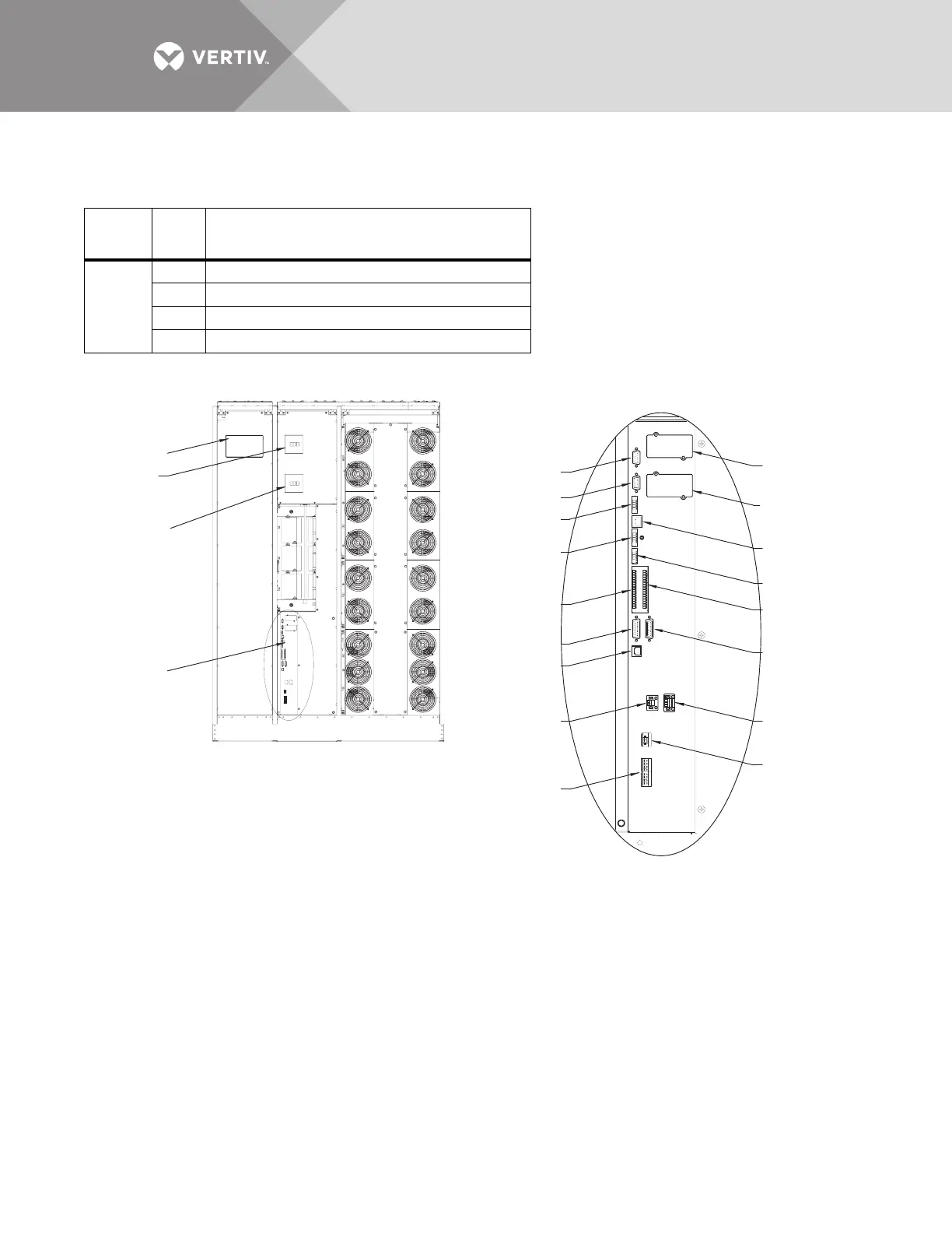
module battery disconnects. See Figures 18 and 19 for TB3’s location on the front of the Liebert®
NX.
Figure 18 TB3 location—225-300kVA Liebert® NX™, SMS and 1+N multi-module unit with static bypass
Table 2 Liebert® NX™UPS control contacts to battery interface boards
Termin
al
Block Pin Connects to (Description of External Item)
TB3
1 CAN +24V - Battery Interface Board TB1154-1
2 GND - Battery Interface Board TB1154-2
3 CANbus High - Battery Interface Board TB1154-3
4 CANbus Low - Battery Interface Board TB1154-4
Control LCD
Main Input
Circuit Breaker
(CB1), optional
Backfeed Circuit
Breaker (BFB)
External
Communication
Panel, See Detail A
X3
X6
XT1/2
XT3/8
X19A
X20
XT2
(Non-Functional)
XS3
XS6 (LIFE)
X9
XT4
X19B
XT1
(Non-Functional)
XB4
TB2
TB3
TB1
Front Doors Removed
Detail A
External Communication Panel
(See specific control wiring drawings)
U38-3C-2000
Rev. 2

 Loading...